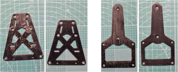
F.R.P. and Carbon parts


Plastic
Plastic is used to manufacture all bathtub-style chassis. This material is chosen mainly for two reasons: ease of processing and low weight. Although plastic is weaker than aluminum and steel, the design flexibility it offers makes it the most suitable choice when aiming to enhance performance. Designers of plastic chassis have several options to increase stiffness without significantly increasing weight:
– adding honeycomb ribs on the bottom to stiffen the structure,
– incorporating fins around the perimeter of the chassis to reinforce the outer frame,
– adding cross members at the suspension mounting points to strengthen the attachment areas.
These solutions increase the final weight of the chassis, but they are more efficient than simply increasing the thickness uniformly throughout the structure, which would lead to a greater weight penalty. As of 2025, plastic remains the most cost-effective material for producing RC model chassis, offering a good balance between stiffness and lightness.
F.R.P.
F.R.P. stands for Fiber Reinforced Polymers and is composed of fibers impregnated with an organic resin. The combination of resin and fibers merges their properties, resulting in a structure with excellent mechanical strength and reduced weight. An F.R.P. chassis can be manufactured in various configurations depending on fiber orientation (e.g. cross-woven, wavy). The more complex the fiber layout, the less space exists between fibers, making the component stiffer.
Tamiya uses F.R.P. to manufacture chassis, suspension mounts, steering arms and other components that share a flat, two-dimensional geometry.
Tamiya immediately began testing this solution with the chassis of on-road cars such as the Williams F1 FW07 F1 CS model 58019, the J.P.S. Lotus 79 model 58020 and the Brabham BT50 BMW Turbo model 58031. The company continued experimentation with the chassis of off-road vehicles like the Rough Rider model 58015, Sand Scorcher model 58016, Ford F150 Ranger XLT model 58027 and Super Champ model 58034.
Development progressed with both the upper and lower chassis of the Toyota Toms 84 C model 58049 and the Porsche 956 Rothmans and Newman models, both coded 58042, culminating in a peak of technological advancement with the Avante model 58072. Over the years, Tamiya has developed various F.R.P. parts available both as standard components and aftermarket accessories.
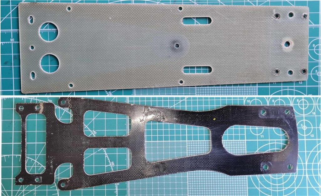
Producing three-dimensionally shaped F.R.P. chassis is too time-consuming; therefore, F.R.P. chassis are flat plates with much simpler geometries compared to their plastic counterparts, which rely on form to enhance stiffness. Nonetheless, the F.R.P. solution remains stiffer and lighter than the equivalent plastic version. In the image below, a comparison is shown between the plastic TA02 chassis (code 10335100) on the left and the F.R.P. version (code 53166 “4WD TA-02 & FWD F.R.P. Chassis Set”) on the right.
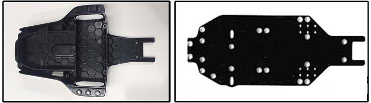
In the image below, a comparison is shown between the plastic TA03R-S chassis (code 50745 “TA03R Bathtub Chassis”) on the left and the F.R.P. version (code 53387 “TA03R-S / F-S F.R.P. conversion”) on the right.
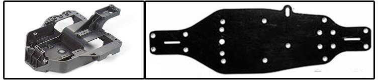
F.R.P. components are on average 6 to 10 times stronger than their aluminum counterparts and 7 to 11 times stronger than equivalent steel parts, while being significantly lighter in weight.
Carbon Fiber
Tamiya later introduced components made of carbon fiber, a solution similar to F.R.P. but lighter and stiffer. Over the years, Tamiya has developed a variety of carbon fiber parts available both as standard equipment and aftermarket accessories. The company uses carbon fiber for manufacturing chassis, suspension mounts, steering arms and other components characterized by a flat, planar design.
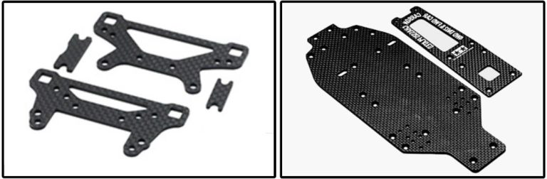
A carbon fiber chassis can be manufactured using various methods, depending on the fiber layout. The fibers can be arranged in unidirectional, bidirectional, or complex woven patterns; each configuration significantly affects the mechanical properties of the final component. In the image below, a comparison is shown between the TA02 chassis in F.R.P. (code 53166 “4WD TA-02 & FWD F.R.P. Chassis Set”) on the left and the carbon fiber version (code 47479 “TA02 Carbon Chassis”) on the right.

In the image below, a comparison is shown between the TA03R-S chassis in F.R.P. (code 53387 “TA03R-S / F-S F.R.P. conversion”) on the left and the carbon fiber version (code 53386 “TA-03RS Carbon Chassis Set”) on the right. Despite having the same external shape, the carbon fiber chassis features more internal cutouts to reduce weight, while maintaining the same torsional rigidity as the F.R.P. chassis.

When comparing the images on the left (F.R.P. chassis) with those on the right (carbon fiber chassis), it is evident that:
– Both F.R.P. and carbon fiber chassis share the same basic two-dimensional design due to the challenge of achieving three-dimensional shaping.
– The F.R.P. chassis is black, whereas the carbon fiber chassis has a dark gray color.
– The fiber pattern is not visible on the F.R.P. surface, while the woven fiber texture is clearly visible on the carbon fiber surface.
In summary, a plastic component is heavier and less rigid than an equivalent made of F.R.P., which in turn is heavier and less rigid than a carbon fiber counterpart. However, plastic allows for more complex geometries.
New F.R.P. or Carbon Fiber Components
Most composite parts are shaped by cutting sheets of composite material using a press. This method allows for the simultaneous production of multiple parts, reducing costs, but the mechanical cutting process leaves the edges rough. Often, a small ridge forms halfway through the plate’s thickness. This ridge can be removed by gently sanding the edges with 1500- then 2000-grit sandpaper. Once sanded, the edges can be sealed with cyanoacrylate to impregnate the lateral fibers.
To finish optimizing the new composite parts, polish the surfaces with abrasive compound to remove glue residues from both top and bottom faces.
Constructing Carbon Fiber Accessories to Enhance Performance.
Sheets, tubes and bars with square or circular sections made of composite material (carbon fiber) can be used to build spare parts or performance-enhancing accessories. Tamiya periodically releases F.R.P. and carbon fiber accessories to boost performance. For flat components such as shock tower plates, gearbox reinforcement plates, or electronic mounts, the following steps can be followed:
– Obtain a composite sheet with the correct thickness matching the part to be replicated.
– Cover the sheet with masking tape to create a uniform surface where the shape of the original part can be traced using a marker.
– Use the original part as a stencil.
– Cut out the shape using a scriber or similar tool, slightly oversizing the outline.
– File the edges with a metal file until the desired shape is achieved—use a flat file for straight or obtuse edges and a round file for sharp internal corners.
This procedure is feasible only if the original flat component is available. Other techniques are required to replicate non-flat accessories. Since we cannot process carbon fiber ourselves by applying resin and curing in a vacuum oven, an alternative is to modify commercially available carbon components to meet our needs. Carbon fiber beams and sheets in various sizes and shapes are readily available on the market. The first step is selecting the appropriate base material. Performance parts are subject to substantial mechanical stress, so choosing between solid and hollow bars affects the final strength of the part.
For example, part number 53323, described as “Carbon Prop Shaft TL01,” is a carbon fiber shaft transmitting power from the rear to the front gearbox in the TL-01 chassis. It is a nearly mandatory upgrade to improve chassis performance and is no longer available new as of 2025. It is possible to fabricate an equivalent carbon shaft with the same shape and mechanical efficiency. Using the factory-installed metal driveshaft as a reference, follow this procedure:
– The original metal shaft has a diameter of 5 millimeters. Obtain a solid carbon fiber rod with the same diameter. A solid rod must be used instead of a hollow one to withstand the torsional loads applied during normal use. Compared to a tube, a solid shaft offers better resistance to torsion due to its higher material density.
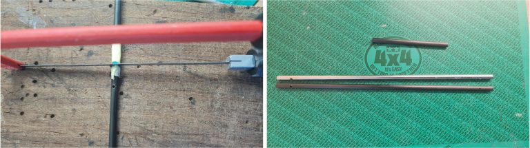
– Using masking tape at three or more points, align the metal shaft with the carbon one so that both ends match. For easier processing, ensure the gear pin holes in the metal shaft are perpendicular to the carbon rod. These holes serve as guides for drilling corresponding holes in the carbon shaft using a 2 mm bit.
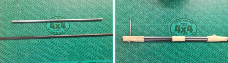
– using the existing holes in the metal shaft as a guide, drill both ends of the carbon shaft with a 2 mm metal drill bit,
– check that the gear pins fit precisely into the holes; they should insert tightly so that the outer surface of the pin is in full contact with the inner surface of the hole. The pins should not come out unless pushed out deliberately with a screwdriver,
– align the metal and carbon shafts so that both ends are flush (see the rightmost image below showing matching shaft ends),
– apply masking tape around the carbon shaft near the point where both parts have equal length,
– mark the exact cutting point on the carbon shaft with a marker to match the length of the metal shaft.
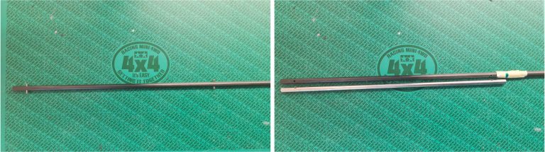
– cut the carbon shaft using a metal hacksaw,
– compare the carbon shaft to the metal one; the image at the bottom right shows the unused section that was trimmed off.
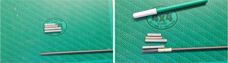
In the same way, it is possible to fabricate accessory 53322, known as the “Hollow Carbon Gear Shaft TL01,” which includes two 40-millimeter shafts, one 35-millimeter shaft and one 30-millimeter shaft used for gear rotation inside the front and rear gearboxes. This part, as of 2025, is no longer available, but it provides a significant performance improvement due to being much lighter than the four factory-installed metal shafts. Below is a sequence of images demonstrating how to construct a 40 mm carbon fiber shaft for the TL-01 chassis:
– the four metal shafts have a diameter of 5 millimeters. They can be replicated using a carbon fiber tube with an outer diameter of 5 mm and an inner diameter of 3 mm, using the original metal parts as templates. The choice between a hollow tube and a solid rod depends on the application; in this case, the gear shaft is subject only to bending, not torsion. Bending resistance is proportional to the moment of inertia, which is greater when the mass is distributed farther from the center. The highest stress is concentrated at the point farthest from the shaft’s center of mass—its outer surface.
Thus, in a cylindrical shaft, maximum bending stress occurs at the perimeter. Using a hollow tube allows for a significant reduction in material while still satisfying load requirements, resulting in additional weight savings.
– align the metal shaft and the carbon tube so that their ends are flush (see the image on the lower right showing both ends at the same level),
– apply masking tape to the carbon tube near the area where both shafts share the same length,
– mark the exact cutting point on the carbon tube with a marker to match the metal shaft’s length.
– cut the carbon tube using a metal hacksaw,
– compare the carbon shaft to the metal one; the image also shows the leftover section, which is ideal for fabricating the remaining three small shafts.
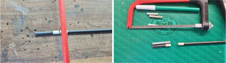
– repeat the same process for the second 40 mm shaft, the 35 mm shaft and the 25 mm shaft.
Restoring F.R.P. or Carbon Fiber Components
F.R.P. and carbon fiber parts cannot be structurally repaired; in the event of a break, replacement is required. However, it is possible to restore F.R.P. and carbon fiber plates that have suffered surface wear over time, for example due to contact with road debris that has scratched or gouged the surface. If the marks are not too deep, they can be removed or reduced.
Treat the carbon parts with abrasive polishing compound. In this way it is possible to reduce the depth of the scratches and make the surfaces shiny; Tamiya provides three different treatments that vary in the grit of the compound. Apply these products in order:
– 87068 “Coarse”, the largest grit used to work the edges of the deepest lines, first row image on the left;
– 87069 “Fine”, the medium grit that removes the marks left by the Coarse, first row image on the right;
– 87070 “Finish”, the finest grit that makes the surface shiny, second row image on the left.
Apply the compound to the surface to be treated and use a cloth to polish the part with a constant, wavy motion until the compound disappears.
If the part has many deep cuts, instead of the cloth it is possible to use a hobby drill equipped with a polishing accessory: a fabric disc.
After the process, the parts should look better than they did initially; if they still show signs of wear, it is not possible to improve further without resorting to more invasive methods. If this method has not produced the desired effect, stronger measures are necessary.
Below is the process for restoring the bottom surface of a chassis that has sustained various impacts from the road surface, leaving shallow and deep scratches:
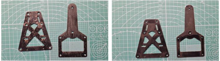
– wash the parts with warm water and dish soap to highlight the damage and remove dirt and grease. In the image below, the left side shows the parts before washing with warm water and soap, while the right side shows them after cleaning.
– cut a strip of 1000-grit sandpaper (this is an example; you can start with finer or coarser grits depending on the depth of the scratches) and attach it to a wooden block, as shown in the image below,
– fully immerse the prepared tool in water,
– wet the surface to be treated,
– work the surface with consistent circular motions until the sandpaper begins to dry. An increase in friction between the sandpaper and the surface indicates it’s time to re-wet the components.
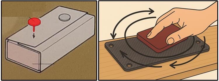
– re-immerse the sandpaper in water and restart the treatment from the first step. If the sandpaper becomes ineffective, it means the abrasive surface has worn down; replace the current strip with a fresh one and begin the process again. If the grit is no longer effective, switch to the next finer grade.
Repeat the above operations using 1200-grit sandpaper (left side in the image below), then proceed with 1500-grit and finally finish with 2000-grit (right side in the image below).
The choice of starting grit significantly affects the final result: if it’s too coarse, it may damage the surface by creating additional scratches; if it’s too fine, it might not eliminate the deeper marks. To determine the appropriate starting grit, test on a corner of the part being restored.
Once sanding is complete, apply a protective surface treatment to the fiber to reinforce and consolidate the plate.
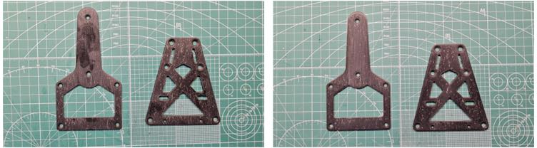
Apply a coat of clear polyurethane paint (preferably gloss) to the freshly sanded surface to protect it and restore its original appearance. The market offers both single-component and two-component spray can options. To carry out the application, follow these steps:
– thoroughly clean the part to remove dust generated by sanding,
– mask the untreated portion of the plate with tape, leaving only the repaired area exposed,
– apply the first light coat of paint using quick, short bursts,
– wait for the time indicated on the spray can before applying the second coat,
– apply a second, heavier coat, again using quick bursts,
– if the result is not satisfactory, apply a third, fourth, or fifth coat as needed (as shown in the lower left image),
– once this phase is completed, lightly wet-sand the surface with 2000-grit sandpaper (as seen in the lower right image) to reduce the gloss, bringing it closer to the original factory finish.
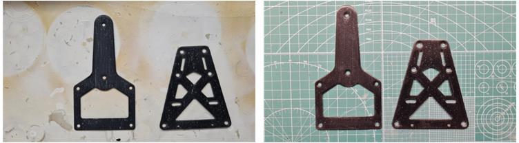
Below are shown the T-shaped chassis and the front subframe of the steering system from a Group C chassis. These parts have been affected by aging, showing several deep scratches and numerous surface abrasions.
On the left, the components appear before the restoration process, while on the right, they are shown after sanding and application of a protective coating. The visual difference before and after treatment is significant; while the parts do not look brand-new, the restoration noticeably improved their appearance.
IMPORTANT NOTE: Working with carbon fiber releases a large amount of fine dust—take all necessary precautions, as it poses health risks.