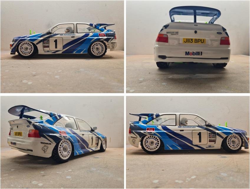
Model
Tamiya Ford Escort RS Cosworth, model number 58112, released in 1993 and available on the market until 1998.
Lexan body enriched with several styrene details: driver’s side mirror, co-driver’s side mirror and rear spoiler.
TA-01 chassis.
This car made history by competing in rallying from 1993 to 1996; its results do not fully reflect its performance. It won eight rallies and reached the podium in the manufacturers’ championship four times: three third places and one runner‑up title. Its success is also linked to the corresponding road‑going version, available on the market from February 1992 to January 1996 and produced in only 7,145 units. Aesthetically, the road version differs from its less powerful siblings mainly due to the double rear wing inspired by the racing version, the front spoiler and the widened wheel arches. The Escort Cosworth is closely related to the Sierra Cosworth, from which it inherits part of its mechanical layout: the Cosworth YB engine is a 1,993 cm³ inline‑four, turbocharged with a Garrett unit, mounted longitudinally with a 16‑valve DOHC configuration. It features permanent all‑wheel drive with viscous couplings on the center and rear differentials, with torque split 34% to the front and 66% to the rear. Its performance is comparable to many sports cars produced today (2026): 227 hp at 6,250 rpm, 304 Nm of torque at 3,500 rpm and 0–100 km/h in 5.7 seconds.
Project
After several TA01 and TA02 restorations, a large number of parts are available on the workshop shelves; combined, they can be used to assemble a complete model:
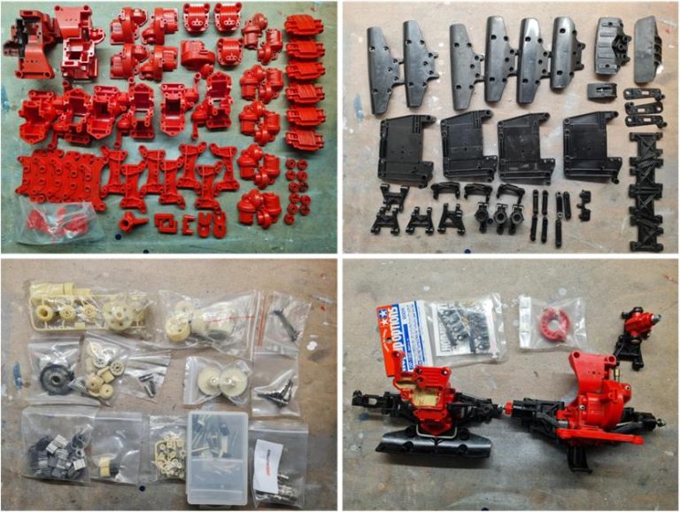
– red plastic parts (image, first row left); many pieces are available and among these loose parts it is possible to select those that are new or nearly new. Some of these components are those most exposed to contact with the ground and may therefore be damaged or scratched during normal use. Despite this, multiple copies of each section are available, making it possible to choose those without scratches or signs of wear
– black plastic parts (image, first row right); among these pieces it is possible to select those that are new or nearly new. Multiple copies of each part are available, making it possible to choose those without scratches or signs of wear
– various gears, drive shafts and universal joints. Each individual component is available in multiple copies, allowing selection of the least worn or new one (image, second row left)
– front and rear sections of an almost complete TA01 chassis
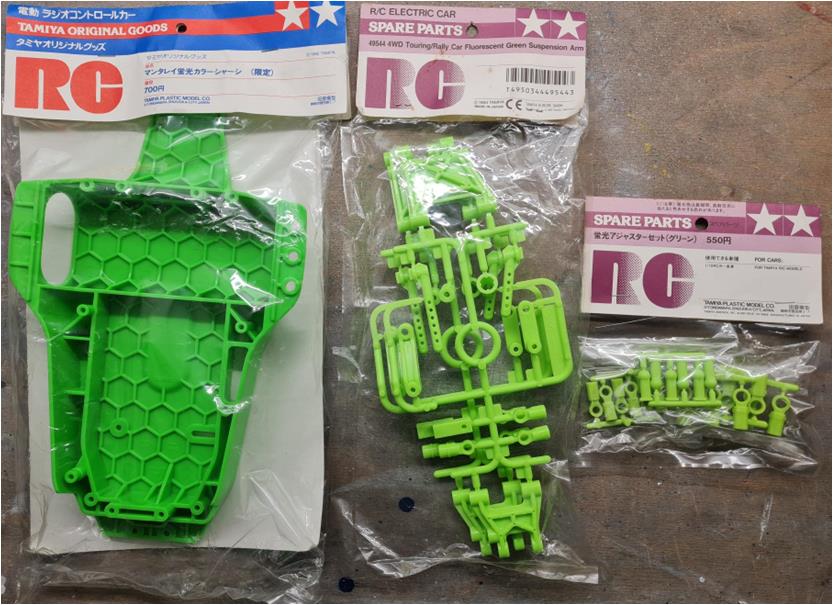
new accessory number 53192, described as “4WD / FWD Touring and Rally Car Turnbuckle Upper Arm Set” (image, second row right)
Suspension arms in fluorescent green, part D (2 pieces per pack), item code 49544. This set also includes non‑adjustable upper arms; it will be necessary to evaluate whether to install the non‑adjustable green arms or the adjustable ones, accessory number 53192.
Fluorescent green chassis, item code 49552.
Ball‑stud joints available in various sizes and shapes; all parts are fluorescent green, item code 49545.
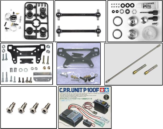
To complete the equipment of this model, the following parts are available (in the image below, starting from the top‑left and moving right and downward):
– reinforced servo saver, item code 50473 described as “Hi Torque Servo Saver Set”
– front wheel axle, item code 50883 described as “39 mm Drive Shaft Set”
– two ball differentials for the front and rear, item code 53070 described as “Manta Ray Ball Differential”
– front FRP damper stay, item code 53193 described as “FRP Front Damper Stay TA01 02”
– rear FRP damper stay, item code 53194 described as “FRP Rear Damper Stay TA01 02”
– lightweight stainless‑steel front and rear drive shafts, item code 53079 described as “Precision Stainless Drive Shafts for TA01/02 and Top Force”
– lightweight king pins for the steering knuckles, item code 53141 described as “Light Weight King Pin Set”; they are not specific to this chassis only because they were introduced on the market later. They fit perfectly and can be considered an accessory suitable for almost all models such as TA01, TA02, TL‑01, DF‑01, M03, M04…
– two‑in‑one electronic unit C.R.P. P100F complete with servo motor+
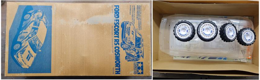
On a well‑known Japanese online marketplace, the following items were sourced:
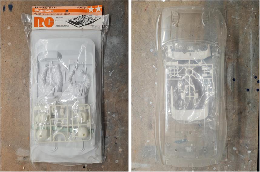
– the body (item code 50484), brand‑new and complete with decals, styrene parts and box (the packaging is in very poor condition, shown on the left in the image)
– the interior cockpit (item code 50463, later replaced by the equivalent 54491), brand‑new and complete with the driver’s helmet, co‑driver’s helmet, steering wheel and gear lever
– four wheels and four tires for the Ford Escort Cosworth (shown on the right in the image). The tires have no markings; they are likely non‑original replicas of the Tamiya product. They will be replaced with rally tires, item code 50476 described as “Rally Block Tires”.
– These are not the tires originally listed in the model’s bill of materials, but today (2026) the factory‑supplied tires are no longer in production and cannot be found on the market. The chosen tires are the same ones Tamiya used on the Lancia Delta HF Integrale 58117.
The project is to assemble a TA01 chassis using new or nearly new parts that best match the freshly sourced body and wheels.
Chassis restoration
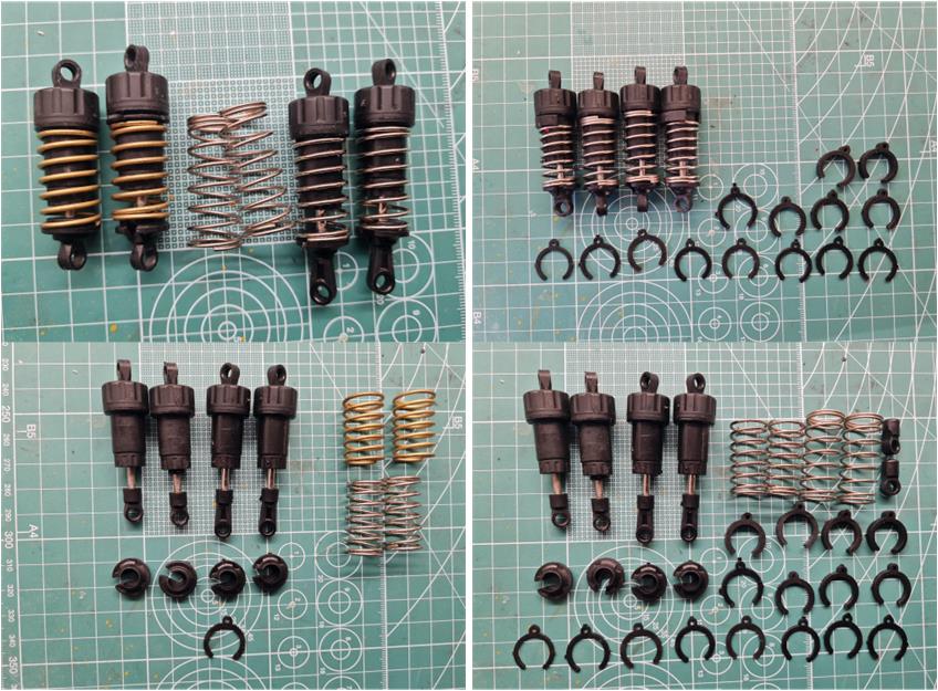
Two pairs of black CVA shock absorbers are available; these dampers are part of the original factory equipment for chassis 58112. They are in good condition and in this case only a full service of all four dampers is required. The operations to be carried out are:
– remove the lower spring retainer to extract the springs,-
– check that the piston moves freely inside the shock body,
– empty the piston chamber and completely replace the oil inside the chambers,
– replace the two gold springs with two equivalent metal‑colored springs,
– replace the ball‑stud joints; two out of four are the long version and must be replaced with the short version,
– assemble the parts, keeping the longer springs for the rear axle,
– the spacers used to adjust spring stiffness will be installed after assembling the chassis and checking how the four suspensions react to load and stress.
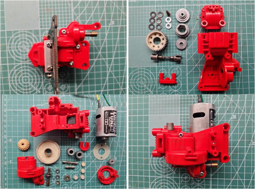
Assembling the chassis is not complex; before proceeding with the construction of the rear section, the best parts with the fewest scratches were selected from those available on the workshop shelves. Among the components already assembled in the rear gearbox housing is the ball differential, item code 53070. The chosen pinion is the 18‑tooth version, more suitable for a rally model. Install the bevel‑gear joint for the rear‑to‑front driveshaft, which is part of accessory number 53079. The selected motor is the “Torque Tuned 25T brushed motor”, item code 54358.
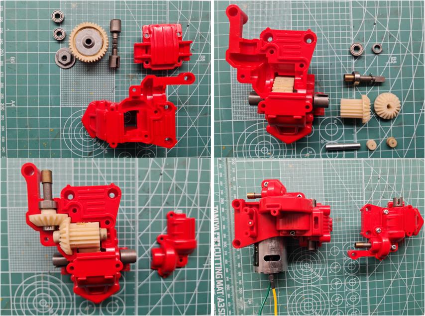
Proceed in the same way for the front section, selecting the plastics with fewer scratches or the new ones available on the workshop shelves. A ball differential, accessory number 53070, has also been installed for the front section. Install the bevel‑gear joint for the rear‑to‑front driveshaft, which is part of accessory number 53079.
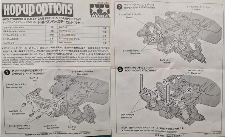
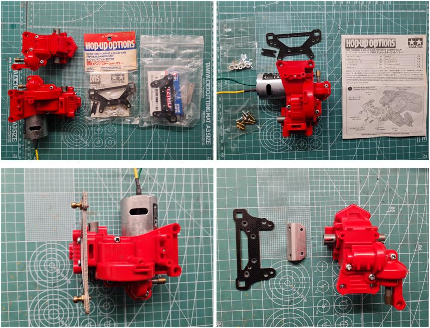
The front and rear gearboxes are ready to receive their respective fiber plates for the installation of the shock absorbers. The image shows the instructions for the rear suspension fiber plate, item code 53194 described as “FRP Rear Damper Stay TA01 02”.
The fiber plates must be installed directly onto the gearbox housing, see images below.
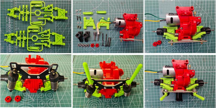
To complete the front and rear assemblies, the suspension arms, shock absorbers, axles, joints and uprights must be installed. The entire drivetrain is mounted on bearings. The parts taken from sprue D, item code 49544, include the fixed‑length (non‑adjustable) upper rear suspension arms, which are installed in place of the adjustable ones, accessory number 53192. To complete the rear block, the two fluorescent‑green body posts are also present.
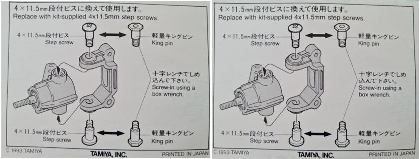
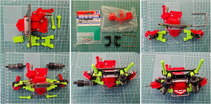
Prepare the steering system by installing the two pins on the right upright and the two pins on the left upright, corresponding to accessory item code 53141 described as “Light Weight King Pin Set”. These pins do not appear as an accessory in the list found in the final pages of the 58112 model manual because they were released only later. For this reason, the original pins will be kept together with the model.
The parts taken from sprue D, item code 49544, include the fixed‑length (non‑adjustable) upper front suspension arms, which are installed in place of the adjustable ones, accessory number 53192. To complete the front assembly, the two fluorescent‑green body posts are also present.
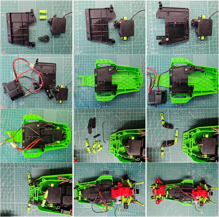
To complete the chassis, assemble the central section consisting of the plastic tub, which houses the C.R.P. P100F electronic unit complete with steering servo and On–Off switch. The fluorescent‑green central tub also contains the dual‑arm steering linkage. The two fixed‑length black plastic steering rods are replaced with two rods of the same length (but adjustable), equipped with fluorescent‑green ball‑stud joints. The central arm also has fluorescent‑green ball‑stud joints. All these parts are included in set number 49544, part D.
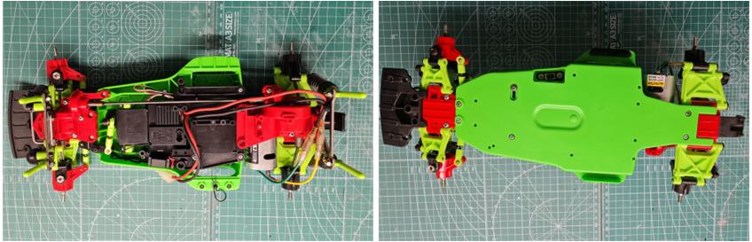
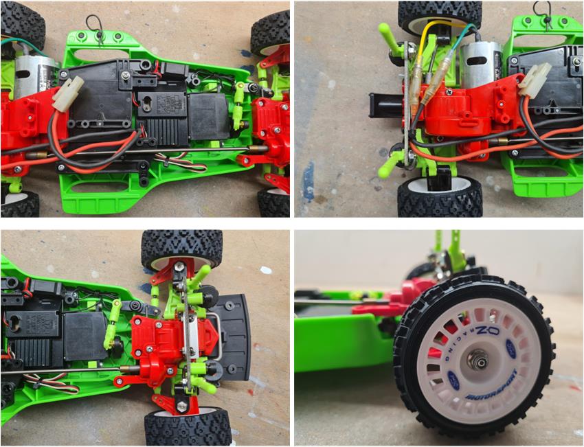
The chassis is now almost complete, with a view shown from above and from below.
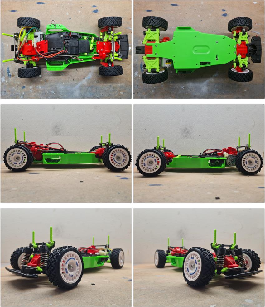
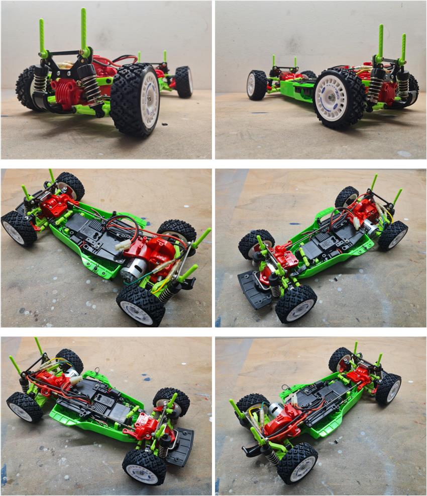
Images of the fully assembled chassis in all its parts, including the newly installed wheels and tires (item code 50476).
Body
Only brand‑new parts in their original factory packaging are available. The body (item code 50484, on the right in the image below), new and complete with decals, is certainly an original piece since Tamiya never released replicas. The interior cockpit, item code 50463 (see image on the left), is the original one and not the later replica sold under code 54491.
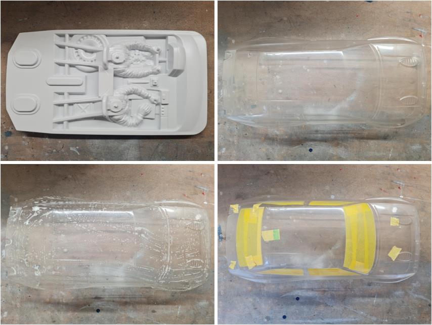
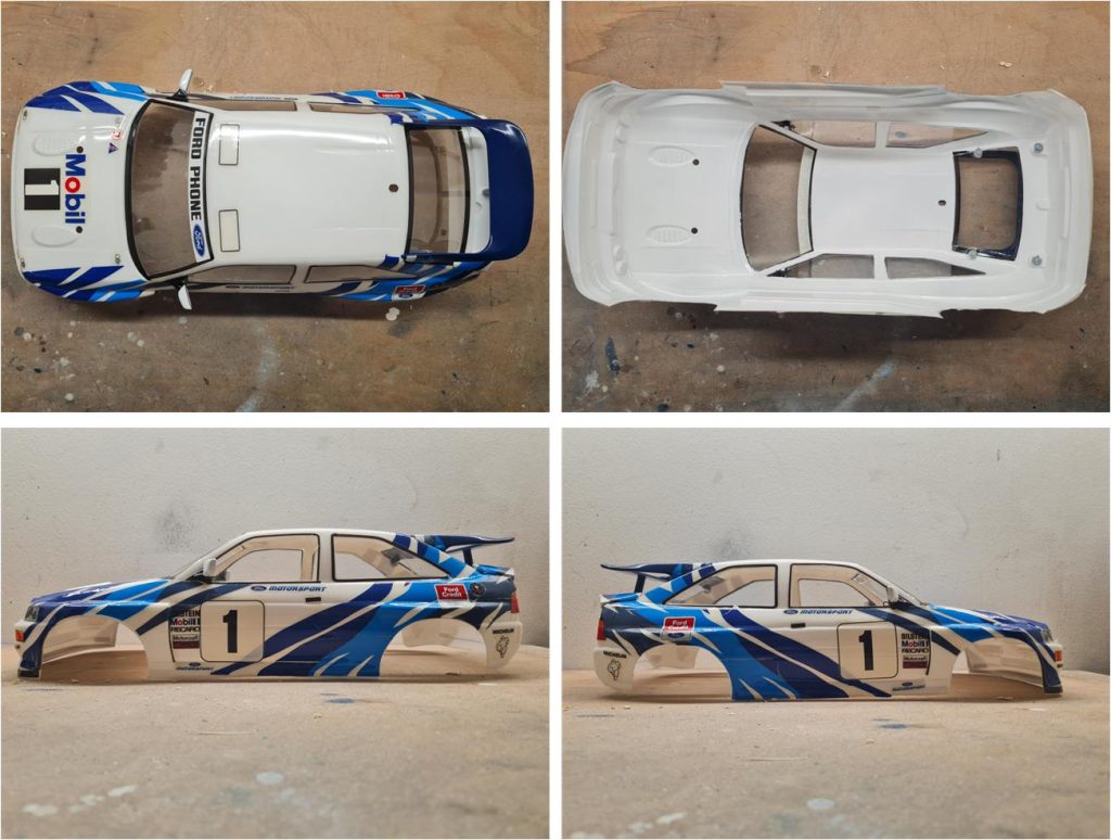
Apply two or more coats of fine grey primer, item code 87026, to all the white styrene parts: rear wing, driver’s mirror, co‑driver’s mirror, driver’s helmet made of two half‑shells, co‑driver’s helmet made of two half‑shells, steering wheel, gear lever and to the interior cockpit, both on the upper and lower surfaces (image on the left of the first row). Trim the excess material from the Lexan body following the demarcation line (image on the right of the first row; the wheel‑arch cutouts are already pre‑cut), wash the inside of the body with dish soap and warm water to remove the release agent used during thermoforming and apply the window masking. Apply two or more coats of PS1 white on the inside of the body. It is better to apply several light coats to avoid excessive paint buildup in certain areas, which could create unsightly drips; applying the paint in multiple passes also allows for a more even finish.
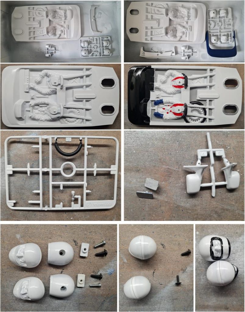
The colours to be applied to the styrene parts are different:
– TS15 blue for the upper rear wing
– TS26 white for the co‑driver’s mirror, driver’s mirror, lower rear wing, co‑driver’s helmet, driver’s helmet and cockpit interior
– TS29 semi‑gloss black for the cockpit dashboard
– X11 silver for the spare‑wheel rim and gear lever
– X18 semi‑gloss black for the base of the co‑driver’s mirror, base of the driver’s mirror, base of the co‑driver’s helmet, base of the driver’s helmet and the visor outline on both helmets
– XF1 flat black for the spare‑tire rubber, driver’s steering wheel, co‑driver’s seat backrest and driver’s seat backrest
– XF7 red for the gear‑knob and the driver’s and co‑driver’s seat belts
– XF8 blue for the driver’s gloves
– XF19 sky grey for the cockpit floor
Once the surfaces have been prepared with the fine grey primer, two or more coats of colour can be applied. Keep the steering wheel, gear lever and mirrors on the sprue; this makes it easier to reach all surfaces, including the more hidden areas. The two helmets must be assembled using the small hardware included in the original package. After that, the various coats of colour can be applied.
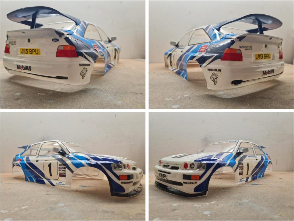
Images of the body complete with decals.
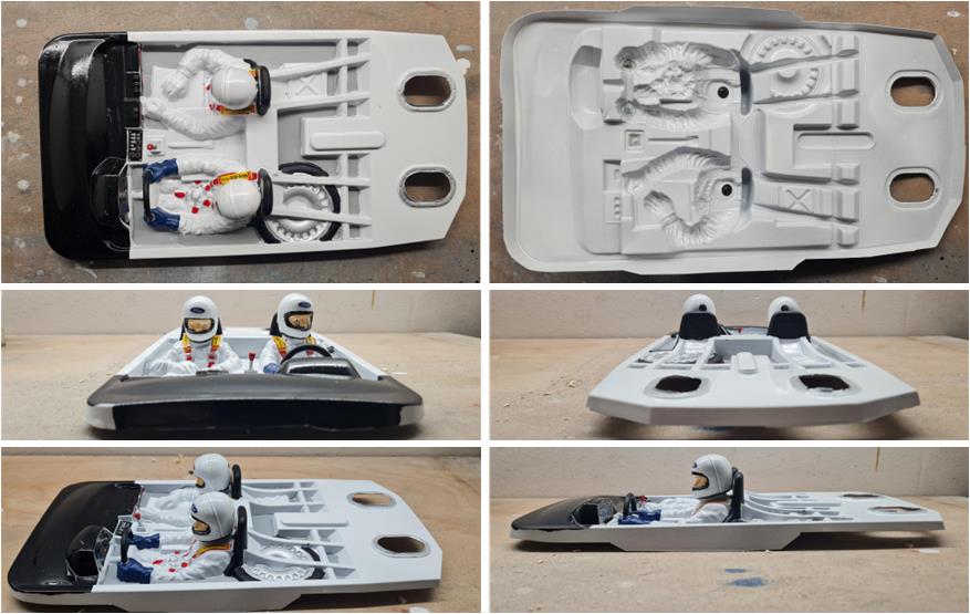
Images of the cockpit complete with decals.
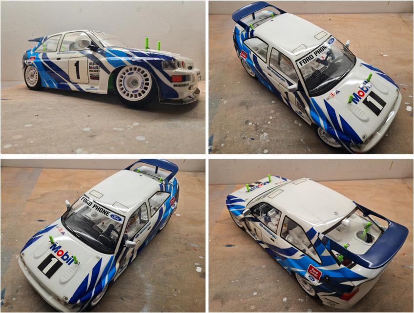
Restored model
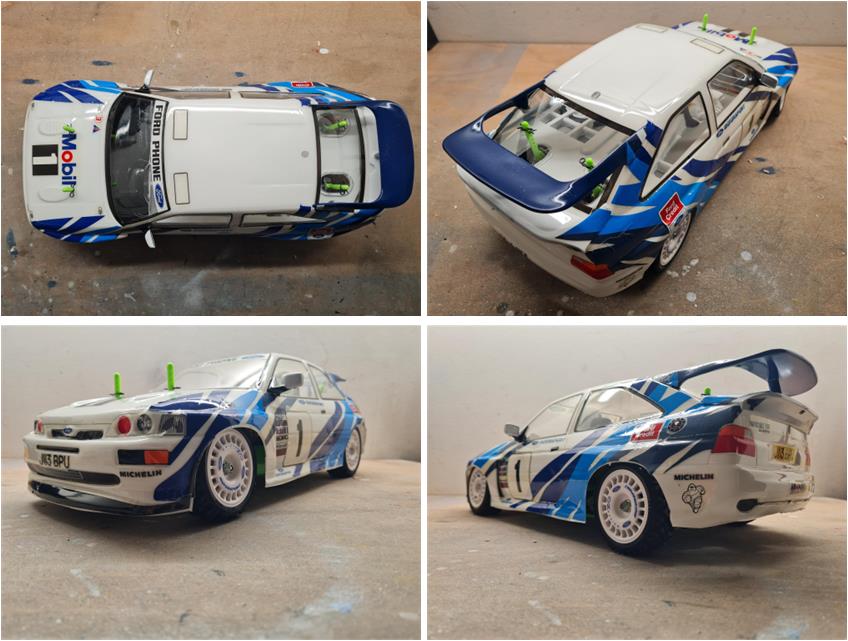
Images of the restored model.