The purpose of this system is to reduce the stress on the gears caused by sudden accelerations, abrupt decelerations and rough landings after jumps and bumps.
A rapid change in load on the driving wheels or a single driving wheel is immediately transferred to the first gear (pinion). The function of this system is to dissipate excess energy, which is absorbed through the clutch instead of being directly transferred to the gears. This ensures more efficient transmission of engine power during acceleration phases, reduces wear on parts during deceleration-acceleration phases and protects the system during landings.
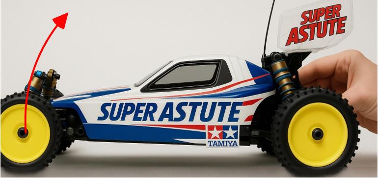
The anti-slip clutch has two functions that compensate for the lack of grip between the surface and the wheels. The first function is to preserve the mechanics during jumps. When the model is airborne, the driving wheels rotate freely without the resistance of the ground, causing them to increase their rotational speed. During long jumps, the motor’s rotation speed is controlled by the operator to maintain the model’s balance and manage the landing angle. Upon touching the ground, the rotational speed of the wheels must quickly align with the actual speed of the model, leading to a sudden change in rotation speed. This puts strain on the transmission gears. This issue is less common in track models, which do not perform jumps high or long enough to cause a major difference between wheel rotation speed and the actual model speed. However, even during short jumps, the clutch remains effective, though its role is less noticeable.
The second function is to protect the gears from premature wear when the engine, during a sudden acceleration, increases rotation speed faster than the wheels can keep up. The same happens during abrupt deceleration. The clutch prevents the model from losing grip and avoids unnecessary stress on the gears.
This dual role ensures the mechanical integrity of the gearbox, where the most stressed gear is the engine’s pinion.
Based on these explanations, the clutch serves two purposes:
– It protects the gears from excessive torque.
– It helps maintain optimal traction on slippery surfaces.
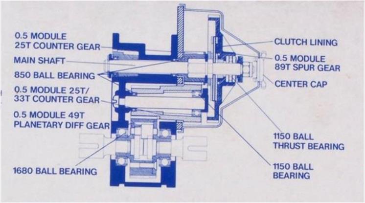
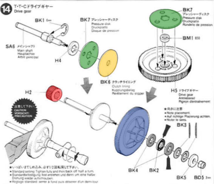
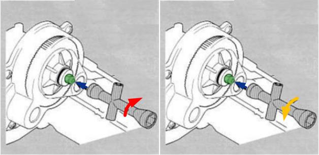
Physically, the clutch system consists of two lateral discs (highlighted in green), which compress the central disc (highlighted in orange) with varying force. The clutch physically separates the larger main cylindrical gear (highlighted in blue in the image) from the smaller second gear (highlighted in red), as it is positioned between them. The slip between these two components is adjustable through the clutch regulation itself. The torque management function depends on the friction between the two lateral discs and the central disc.