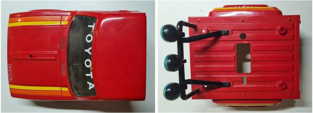
Model Tamiya Toyota Pick Up 4×4, model number 58028, released in 1981 and available on the market until 1984 Styrene body divided into two parts: the front section includes the hood with the cab and the rear section includes the widened track bed that covers the radio box. The front part was used as the base for the Bruiser model 58048 and Mountaineer model 58111. To complete the body, there is a roll bar with three lights and a cockpit with a driver. 3-speed chassis It is probably one of the most famous models made by Tamiya alongside the Blazing Blazer.
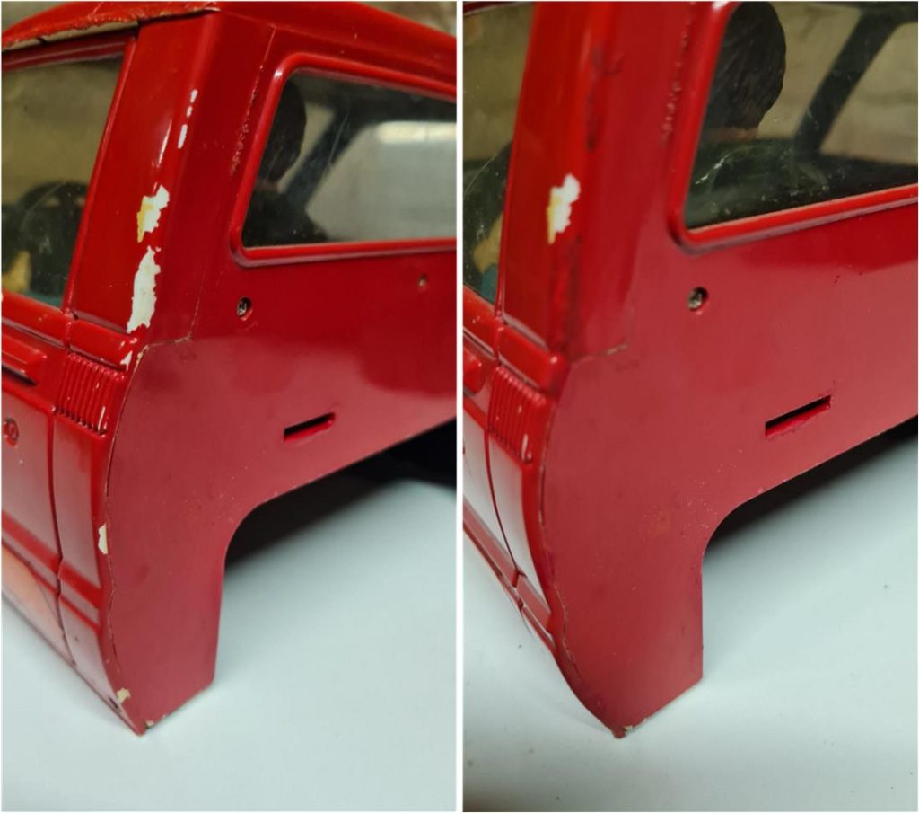
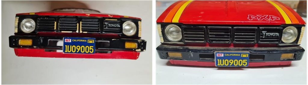
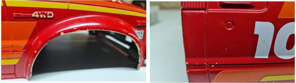
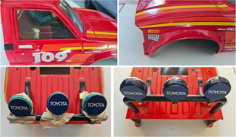
Model restoration analysis The starting point of this restoration is a question mark. From the pictures, you can see that the body has been painted according to the manual, maintaining the official color scheme and correct placement of the decals. The body includes all the parts: radiator with lights and license plate, hood with cab, rear bed with lights and license plate, cockpit with driver figure, windshield with intact windows and roll bar with three lights. The body shows some areas where the paint has come off, which is a problem because if a conservative restoration is desired, it’s hard to replicate the same shade of red. Some tests can be done; time, sunlight and artificial light have surely altered the color, so it’s very difficult to find the exact match. However, the areas that lost color are small, so a conservative body recovery attempt is possible. If the final result doesn’t meet the required standards, the body will need to be fully restored. The starting point is excellent, as it is complete and with no signs of breakage.
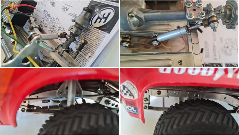
The same situation does not apply when observing the chassis. The previous owner modified the chassis by adding front fenders, rear fenders and an underbody. The intention was to protect the body and the upper part of the chassis. These elements are made of metal sheet and are well finished, but it’s a personal initiative that does not appear in the list of official accessories or accessories produced by companies other than Tamiya. This modification further increases the weight of the chassis, putting additional strain on the wheels. The tires are rubber with a tread pattern that perfectly replicates that of a real off-road vehicle. A unique feature of this model is the hard plastic inserts that create a wave-like motion typical of the Pick Up when driving over uneven terrain, reminiscent of a gondola tossed by the sea. Instead of dampening the unevenness, these inserts amplify it. All four wheels with aluminum rims are present and appear to be in good condition. The four black hub covers are also present. Additionally, there are two spare wheels complete with rims and two wheels without rims. Excellent spare parts to keep for future restoration work on similar models.
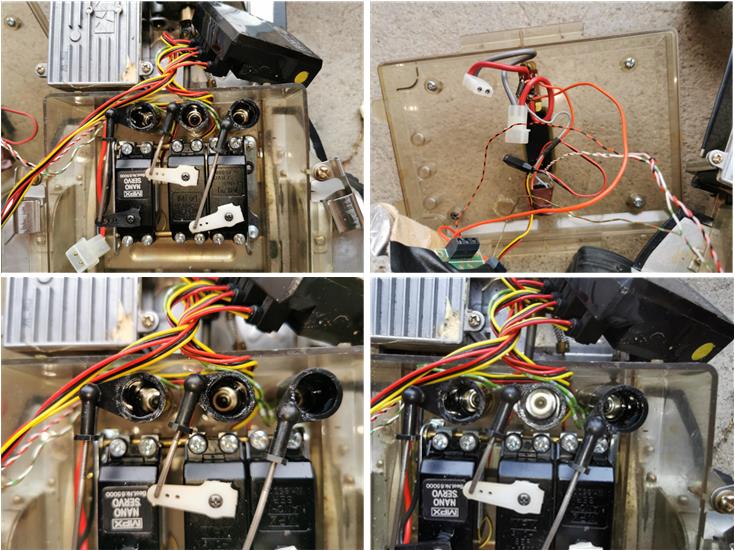
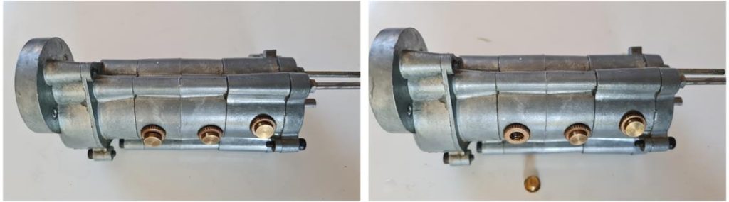
The gearbox does not feature the three pyramid-shaped rubber caps but instead has three brass caps that appear to allow inspection of the gearbox. This is not a period accessory, but in this case, they seem to be a good solution that needs to be carefully evaluated whether to keep or not. As of today (2025), the market offers the three cones for the Bruiser reissues, accessory number 300051499 described as “Rubber Band, Part Set B.” This set contains, among other parts, four rubber cones that act as caps for the three inspection points.
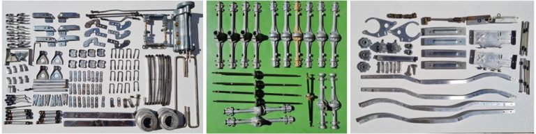
The rest of the chassis appears to be in good condition, but it’s necessary to check what modifications were made to install the metal understructure. All parts are present: the front and rear axles are complete and in good condition, the four leaf springs, four oil dampers, speed control system, cross members and two side frames… There are no visible signs of rust.
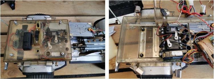
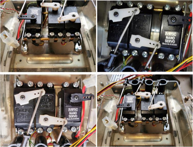
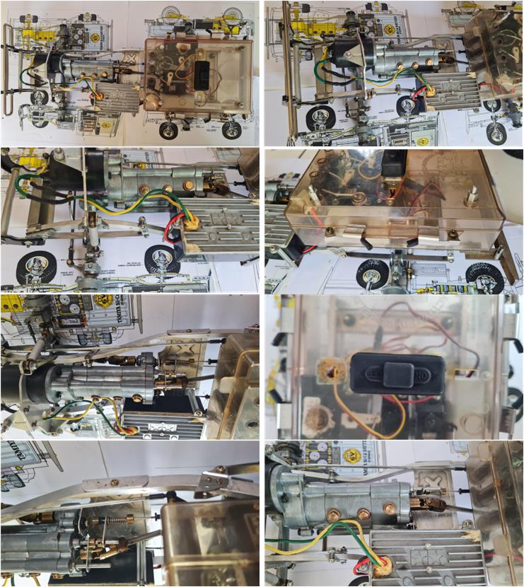
The electronics box is complete with both shells. The closure system, consisting of four quick-release clips, is also complete. The upper part of the shell where the switch is housed has been modified; this section has been shaped to better accommodate the large switch that Tamiya included in some kits. The modification appears well executed and does not decrease the model’s value. From the images shared at the time of purchase, it is possible to evaluate the three servo motor cams and the servo motor mounting system.
The three servos are present to control the steering, the electric motor speed and the gearbox gears. The three cams used to transfer the movement from inside the electronics box to the outside are also present and appear to be in perfect condition. The dual-plate mounting system for installing the three servos is in excellent condition and all 12 screws to secure the servos to the structure are present.
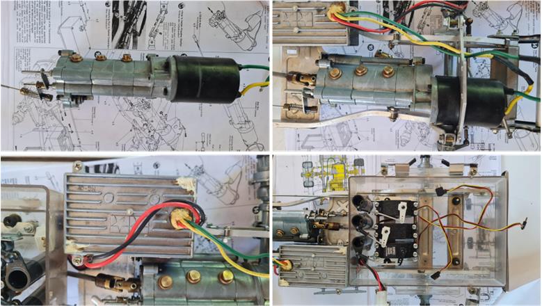
Analyzing the previous and following images, it is clear that in addition to the standard electronics, there is an incredible amount of wiring, two electronic boards and a buzzer installed next to the motor. The electronic boards are used to control the lights and the buzzer that simulates the horn.
When the model arrived, there were no particular surprises. Before proceeding with the purchase, the seller provided a complete set of detailed images that revealed everything. For the restoration of this model, many spare parts are available, preserved from previous restoration work done on the Pick Up 58028 or the Blazing Blazer 58029. After disassembling the model and cleaning the parts, the main task is to select the best from what is available.
Chassis restoration
The first step is to disassemble the chassis to check each part; during this phase, look for broken parts, missing parts, modified components, screws that won’t come loose…
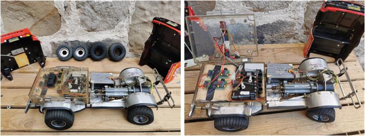
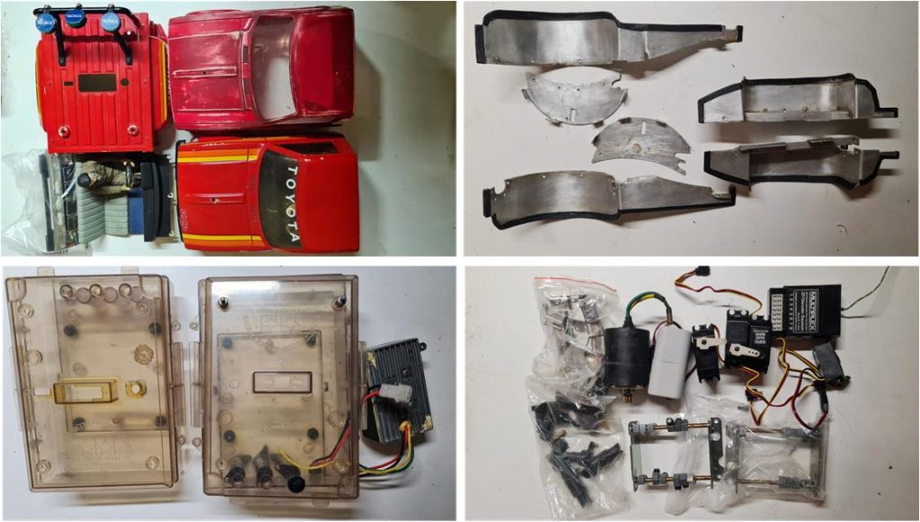
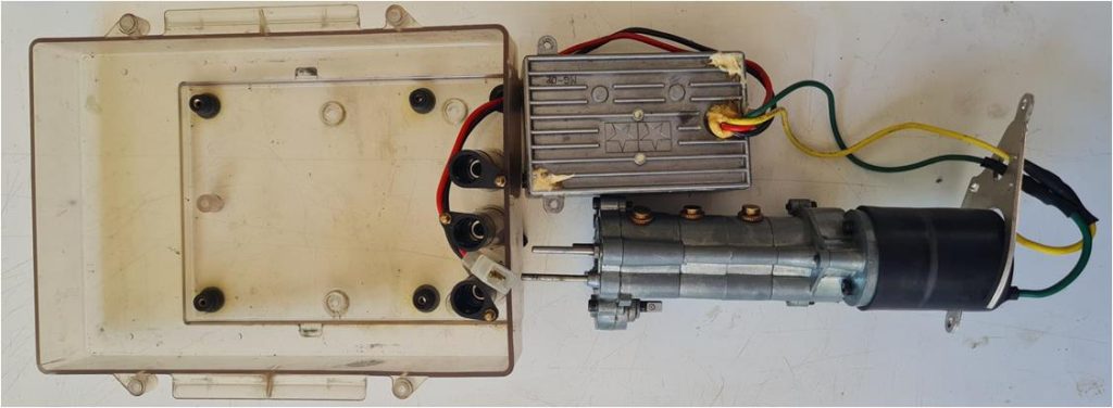
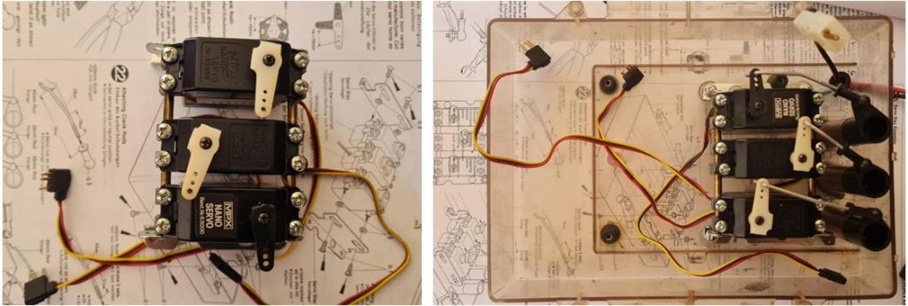
– Separate the two-part body from the chassis (in the first row on the left in the image). A spare front section is available, complete with driver figure, cockpit and front grille. The condition of the original body is better than the available replacement. – Remove the four wheels along with their hubs. – Dismantle the fenders built by the previous owner and set them aside (first row on the right in the image). – Remove the front axle with its leaf spring suspension, which includes the steering system and the rear axle with its leaf spring suspension. – Remove the electronics box; in this case, the battery plug has been correctly installed and connected to the cable inside the electronics box (second row on the left in the image). – Separate the electronics from the electronics box. A spare mounting frame is available for installing the three servos (second row on the right in the image).
– Disassemble the full side-frame chassis along with its cross members and bumper. – Remove the aluminum rims from the tires.
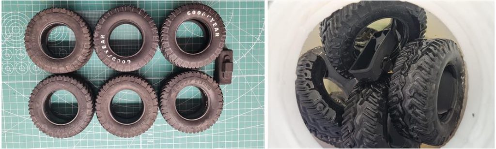
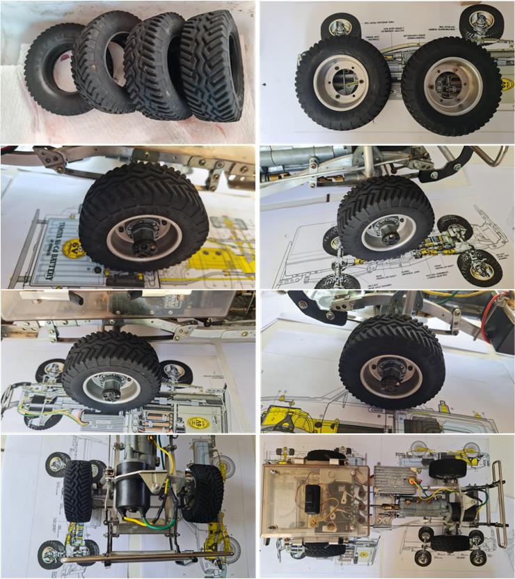
First, the tires must be treated. The four tires contain a rigid insert that causes the typical wave-like movement during normal driving of this model; terrain roughness is absorbed only by the leaf springs. There’s no need to risk damaging the tires by extracting the plastic insert. The tires are treated with glycerin, which has no effect on plastic, so all parts can undergo the regeneration process. For the tire regeneration procedure, refer to the article in the restoration section. In the images below, the four tires originally installed on the chassis and two spare tires are shown after washing with hot water and dish soap (on the left in the image below) and immersed in glycerin (on the right in the image below). All these tires show no tears or cracks. Rubber regeneration takes about three to four weeks. Along with the four tires, the on-off switch cover has also been included. The rubber cylinder that covers the electric motor is in good condition and does not require treatment. Moreover, this rubber cylinder is tightly fitted onto the electric motor and could be damaged if removed. In such cases, if the rubber is still soft and intact, it’s better not to proceed with regeneration.
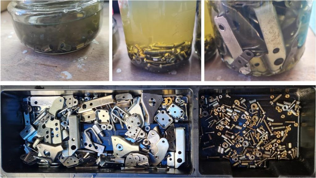
The metal parts are used and covered with a more or less thin layer of dust and grease. Perform a thorough cleaning with water and soap and then immerse the parts in diesel fuel. The parts were divided into three groups based on their size (images of the three jars in the first row). The first group contains screws, nuts and bolts up to 2 mm in size; the second group contains screws, nuts and bolts up to 5 mm; and the third group includes all the small parts that make up the chassis. The parts were placed in three glass jars with airtight lids. Once the small components are placed in the jars, pour diesel fuel generously to fully cover all the pieces and close the lid. The diesel treatment lasts for a week, up to a maximum of ten days; during this time, the metal parts lose all traces of oxidation, grease and rust. After the treatment, leave the parts in the sun—diesel evaporates and leaves a shiny protective coating on all surfaces (image in the second row).
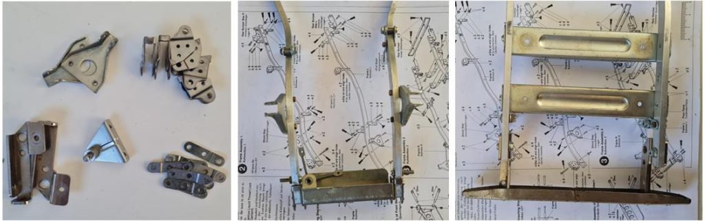
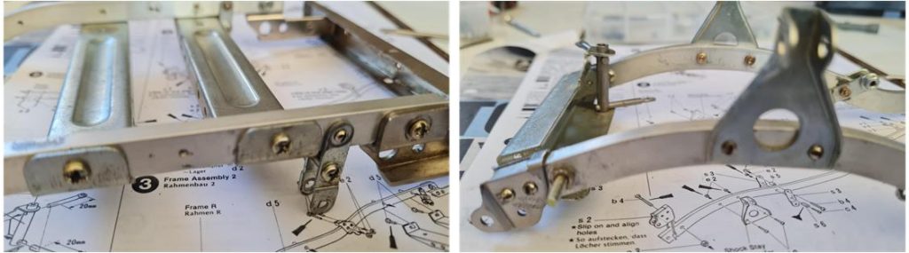
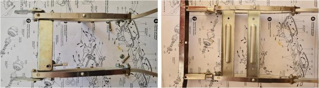
Sequence of pictures showing the steps in which the frame is assembled.
– before assembling the parts, select from those available the best ones that do not have any scratches or stains; – complete the right and left side members with the leaf spring suspension parts, – install the rear bumper (this part is delicate and often has not survived impacts), the two rear cross-members, the motor mounting plate and the front plate with double 90° steering arm.
At this stage of the restoration check all the small parts, for the 3 Speed frame all the 2 mm frame screws are slotted head. Over time it is possible that some have been replaced so it is important to check and if necessary replace the wrong ones. After treatment with diesel oil, kitchen soap and hot water the spars still show some machinery which is due to friction between moving parts. Aluminium becomes darker at these points; it is better not to mechanically treat the surfaces with sandpaper. When assembly is complete, these defects will not be visible.
Installing the leaf springs on the ladder frame, which is now ready to receive the transmission system with electric motor, electronic box and the two front and rear axles. The leaf springs are made of three steel blades. The Toyota HiLux Pick Up model is characterized by a bumpy ride caused by several factors: hard plastic inserts in the four tires, suspension that poorly absorbs rough surfaces, wheels with too small a diameter and excessive weight of the chassis – transmission unit – motor – electronics. Over time, some have removed the smallest blade to better absorb irregularities, but the leaf springs on this model still retain the original three elements. Front leaf spring system in the image on the left (showing the two bumper mounting plates) and rear leaf spring system in the image on the right.
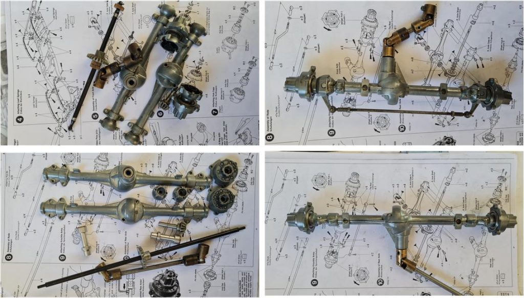
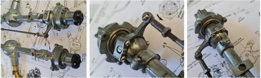
Assembling front and rear axles. Both axles are equipped with hubs and black plastic hub covers. The front hubs allow selection between having the front wheels free when the model is in reverse, or linked to the movement in both forward and reverse gear. The front system is complete with linkages for the steering mechanism.
As with the other parts of the chassis, check that the 2 mm small hardware has a slotted head.
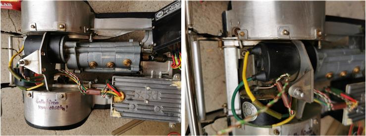
The gearbox does not have the three rubber plugs, but instead features three inspectable brass plugs. The central part is screwed onto the outer ring (see image on the right), which in turn was fastened to the outer casing of the gearbox. This solution did not affect the functionality of the gearbox and is very practical. Since it does not compromise the outcome of the restoration, the three brass plugs have been kept. The gearbox was externally cleaned using a cloth soaked in diesel fuel.
Install the electric motor onto the gearbox, inserting the rubber insert which should enhance protection against dust, mud and water. Complete the connections from the electric motor to the speed controller (yellow and green cables) and from the speed controller to the electronics box (red and black cables). When assembling the yellow and green cables, pay attention to the teardrop-shaped plate that supports the front of the electric motor and to the rubber motor protection sheath. Both parts should be positioned before soldering the cables together with tin. Assemble the three black cams for the movements of the servomotors, which are installed at the front of the electronics box.
Assemble the tower structure that allows the three servomotors to be mounted, with each servomotor secured to the structure using four screws (image on the left). The control rod should be slightly bent to better transmit the movement from the servomotor arm to the cam arm. Once the three servomotors are fixed to the metal structure, fasten the assembled unit to the electronics box (image on the right).
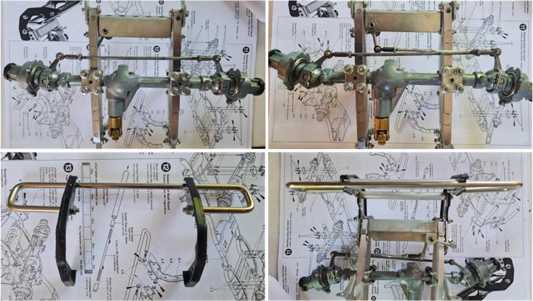
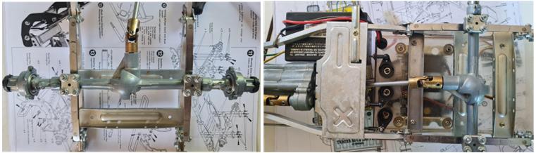
It’s time to assemble the chassis to the front axle, the rear axle, the transmission–motor system, the speed controller and the electronics box. Start from the front section, where the axle with the steering system is located, along with the double lever to transfer motion from the servo motor and the front bumper.
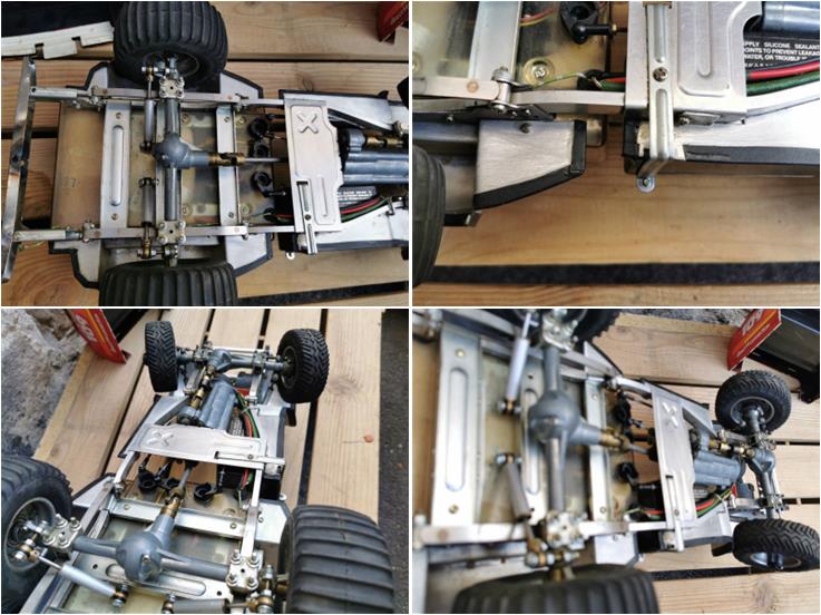
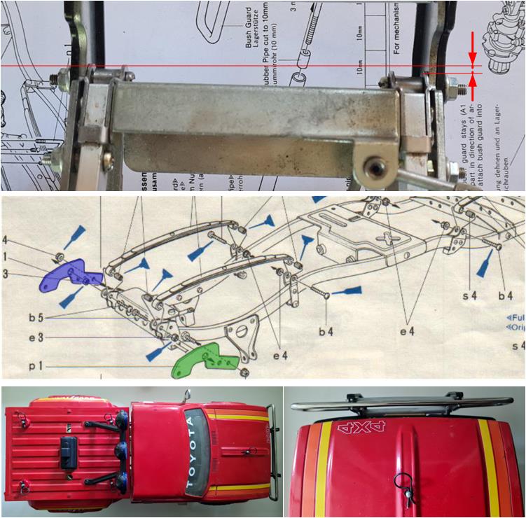
Be aware that the 3 Speed series chassis are often offset—the two frame rails are parallel, but the construction using cross members fastened with only one screw per side leads to misalignment of the rails (see image in the first row where the two red lines highlight an offset of 2–3 mm). To prevent the bumper from being tilted relative to the front of the body, check the two plates that support the bumper (highlighted in blue and green in the second row image). These plates are always slightly different in length. Install the shorter plate on the side where the frame rail protrudes more to reduce the chassis misalignment. In the third row, the final result is shown after the body has also been installed.
Install the rear axle, which does not include any steering linkages.
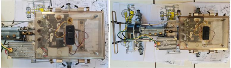
Install the motor onto the gearbox to build the motor and transmission system. The motor should be wired to the speed controller, which is a model specifically developed for the Toyota Pick Up 4×4, model number 58028. The battery cable must be wired inside the transparent electronics housing box.
After installing the electronics, the electronics box must be completed. There are four tabs that allow the lid to be secured onto the lower tray. Once the box that protects the electronics from mud and water is finished, the chassis is ready to be joined with the body.
Due to the hard plastic inserts inside the tires, the Tamiya Toyota Pick Up 4×4 is known for its distinctive rocking motion, reminiscent of a boat tossed by waves. To dampen this motion, Tamiya provides the installation of four oil shock absorbers as an optional accessory. In some countries, the importer included this accessory with the kit; in others, it had to be purchased separately. In this model, they are present.
The chassis is complete and all its components have been installed: gearbox with motor, speed controller, box to protect the electronics from dust – water – mud, front bumper, rear bumper with antenna mount, receiver, three servos, front and rear axles.
The wheels have been refurbished and are mounted on the rims, which consist of two aluminum half-shells joined together by three plus three socket head screws. The tread has a designated direction of rotation, so the wheels must be installed according to the tread’s construction.
Body restoration
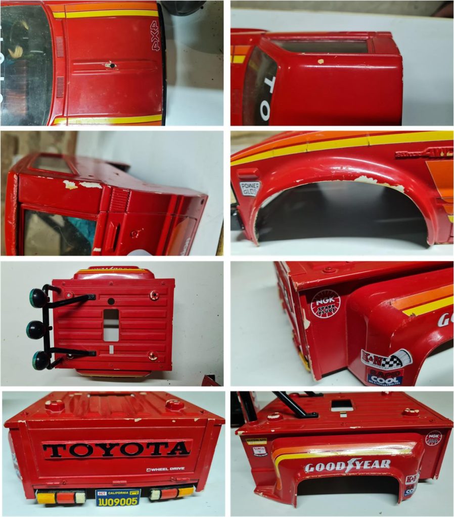
The body is essentially composed of the front and rear sections. The cabin and driver figure are intact and in good condition, so no restoration work is necessary; the patina that has formed over time clearly shows that this is a product from the 1980s. The front and rear body sections are also in good condition, apart from a few spots where the paint has chipped off. Most likely due to impacts, the paint has cracked and peeled away; however, the rest of the finish was professionally applied. In the images below, the front and rear parts of the body are shown and the small areas where the paint has come off are clearly visible.
To preserve the decals, red paint can be applied to the areas where the original paint is missing and then blended using wet 3000-grit sandpaper. This process softens the newly applied color and harmonizes the overall appearance, since it’s impossible for today’s paint to perfectly match the one used 40 years ago. Exposure to sunlight, artificial light, dust, cleaning agents and household gases like perfumes or aftershave has undoubtedly altered the original red tone. To determine the right color, testing is the only option. In the image on the left, the body shows the missing paint areas; in the image on the right, two attempts are highlighted to evaluate which color best replicates the original. This section was chosen because it’s hidden when the body is mounted on the chassis. The first test was done with X7 (“Red”) on the lower part and the second with TS8 (“Italian Red”) on the upper part. The best result is achieved with X7.
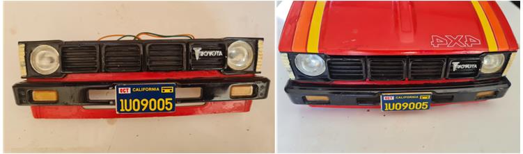
Sandpaper is used to soften the transition between the paint applied by the previous owner and the paint used to cover the spot where the white body is visible. The goal is to carry out a conservative restoration that repairs the body without losing the originality that time has given it. The same procedure should be applied to all parts of the chassis, such as the front grille—image on the left shows the grille before treatment and on the right after treatment.
There are some parts (handles, grilles and Toyota logos) that will need to be refinished; the main colors listed in the instructions are:
– white X2; applied to the indicators on the front grille, license plate borders and reverse light – red X7; used to cover the blemishes on the body and the rear brake lights – orange X6; used for the side turn signals – Chrome Silver X11; applied to the front Toyota emblem and other small details such as door handles and the side window trim – Flat Black XF1; the largest area of application is the front grille, but it is also used in several other places such as the rubber seals of all cabin windows, the side grille near the doors and the rear of the three lights on the roll bar – Blue X4; for the front of the three lights on the roll bar
This is the front and rear body with the red paint “touch-ups.”
After applying the drop of red paint, allow time for it to dry and then treat the areas with wet 3000-grit sandpaper to blur the transition between the two colors. The following details must be painted:
– Directional arrows on the right and left sides of the front section with X6 Orange – Side grilles behind the doors with XF1 Flat Black – The three lights on the roll bar with X4 Blue – Door handles and the lock with X11 Chrome Silver
In some cases, masking is recommended; for smaller parts, a steady hand is enough to achieve an excellent result.
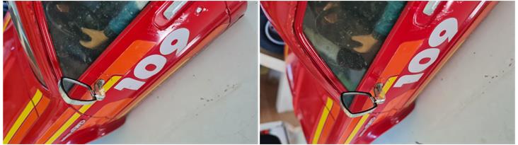
The rearview mirror was missing from the model received by mail, but luckily it was found among spare parts from previous builds and has been installed. As per the instructions, only the driver-side mirror is included. The cabin and driver figure were painted by the previous owner; to preserve the aged patina, no restoration work was done and the original paint was left untouched.
The grille was restored using X1 paint, while the Toyota emblem was decorated with X11 paint, which is also used for the side emblems. Install the grille on the front section of the body. The lighting system, dating back to the 1980s, was not disassembled. Both front and rear license plates are present and feature the original stickers and the body includes the rear lights. Choosing to refurbish the body allowed the original decals to be preserved.
The body is now ready to be mounted onto the chassis.
Restored Model
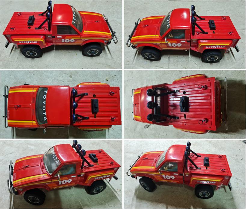
Images showing the completed model.
Tamiya, original figure, box art, guide book and catalogue are of TAMIYA INC, which does not endose or sponsor www.tamiyaclassic.com. Any brands, logos and trademarks represented on this website are the copyright of their respective owners.