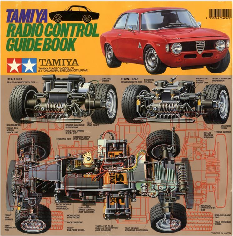
Tamiya Alfa Romeo Giulia Sprint GTA, item number 58187 released in 1996 and available on the market until 2002. Lexan body. Chassis M-02M, medium wheelbase of 225 mm. This model replicates an iconic car in Alfa Romeo’s production.
In 1964, Alfa Romeo entrusted Autodelta with the task of developing the Giulia Sprint GT for track racing. The mechanics were modified by redesigning the electric motor to deliver 170 HP and the body was lightened by replacing the external panels (hood, fenders, two doors and roof) with identical aluminum parts, keeping the aesthetics unchanged. A careful analysis of the regulations allowed Alfa Romeo to homologate a two-door body with four seats: in the GTA version, the rear seats were replaced by a small bench to meet the minimum cockpit dimensions required by the sport regulations. The acronym GTA stands for Gran Turismo Alleggerita—indeed, it weighed only 745 kg, about 200 kg less than the original version. The sporty version of the Giulia went through several evolutions such as Alfa Romeo Giulia Sprint GTA SA (Supercharged), Alfa Romeo Giulia Sprint GTA 1300 Junior and Alfa Romeo Giulia Sprint 1750 GTAm; it remained in production until 1975.
Model analysis for restoration
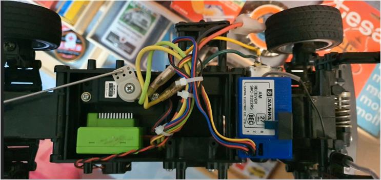
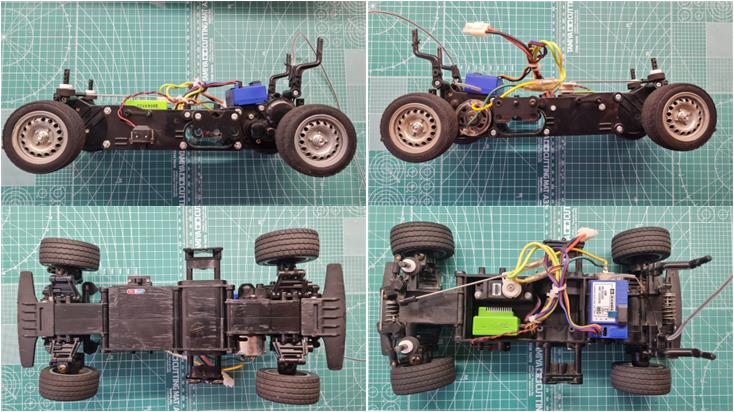
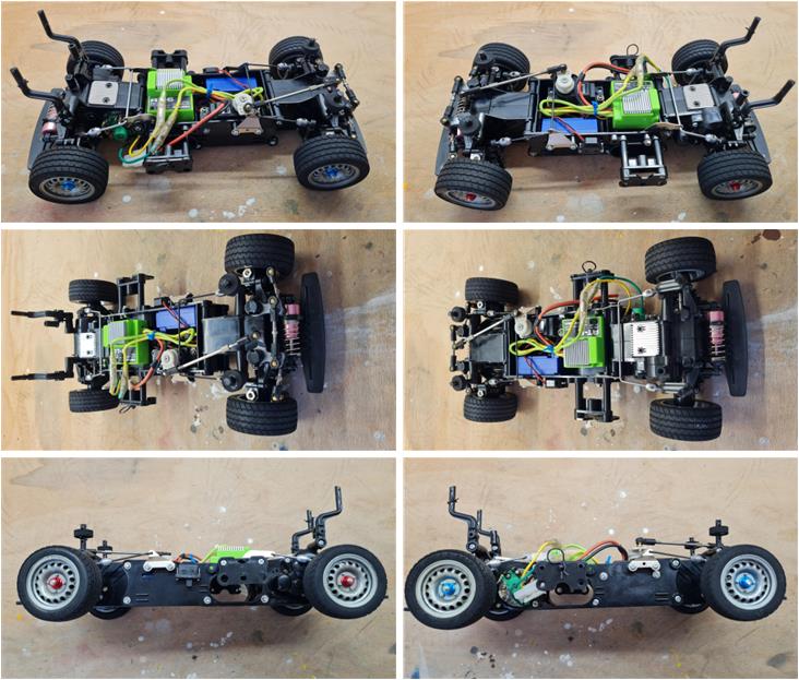
When purchasing online, it is only possible to visually analyze the images in the listing to assess the condition of the chassis; in this case, there is only one photo that reveals very little about the state of the underbody. Note: the M-01 and M-02 models have a central chassis made up of two plastic shells. Ground clearance is very low and they often scrape the ground and get damaged. The suspensions are very sturdy and rarely break unless in very violent impacts. Most chassis suffer from excessive play in the steering linkages. With only this photo available, few visual checks can be made on the chassis. An electronic speed controller, steering servo and receiver are present. No other installed accessories are visible.
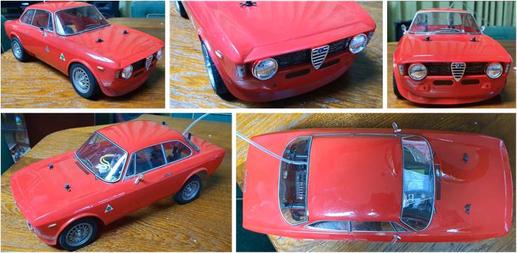
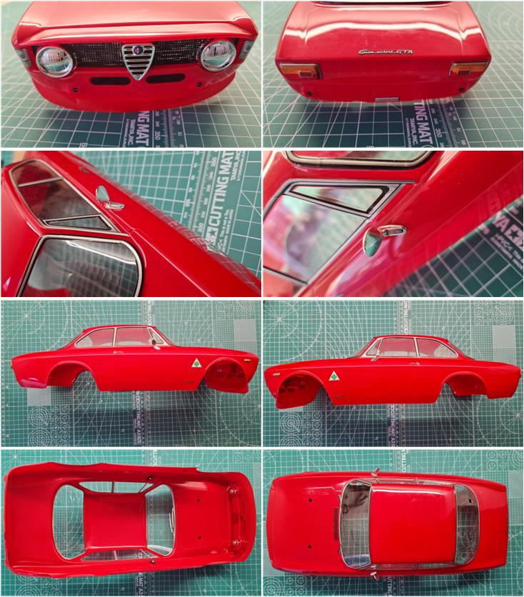
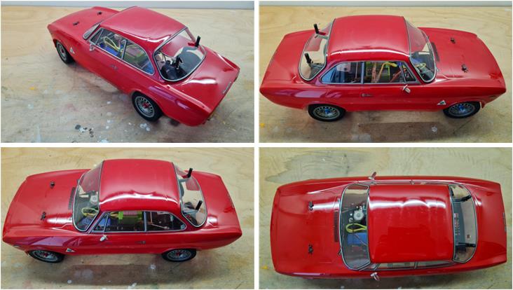
It is possible to visually analyze the images from the online listing to assess the condition of the body; unlike the chassis, there are several photos available for the body and it is noticeable that:
– the body shows no visible damage, – the red color is the official one of the Tamiya model and the typical Alfa Romeo red, – both rearview mirrors are present and intact (they are usually the first to break along with the front grille). The only difference compared to the catalog photos is the color of the windows, which have been left transparent instead of tinted black; honestly, this is a solution I prefer because it allows visibility of the chassis even with the body installed, – the front grille with two headlights and the typical Alfa Romeo front end is present, – the decals have been correctly applied and – all four wheel rims appear intact and unworn.
These photos seem to confirm a good state of preservation; the previous owner took care of the model.
When the model arrived, chassis inspection showed that:
– wheels and rims are in perfect condition, – no parts are missing and the chassis matches the factory configuration exactly, – there are marks on the underside of the central chassis, but they are not very pronounced – both front and rear bumpers are present and show no obvious signs of impact, – the four body support posts have been cut to reduce their protrusion from the body.
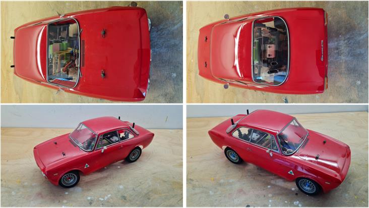
When the model arrived, body inspection confirmed what was seen in the online listing photos:
– the front and rear sections are in perfect condition, with no signs of impact, – both rearview mirrors are in perfect condition, – the window trim has been applied according to the manual, – all the decals provided for this model are present, – the internal and top views of the body show no defects. The body has been assembled and painted with great care, almost resembling a factory product, but upon closer inspection, there are slight imperfections in the paint application typical of manual work.
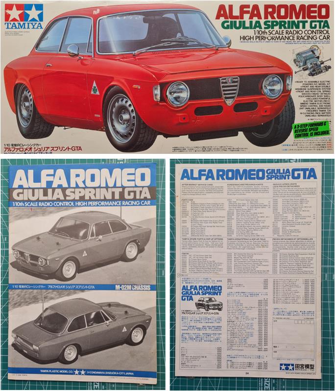
Along with the chassis and body, the instruction manual and original packaging arrived. The packaging includes a small red box for components and small parts, featuring the Alfa Romeo logo. In addition to the electronic speed controller, the mechanical one is also present. Both the packaging and the small box are in perfect condition. The instructions show no marks or tears.
Alfa Romeo Giulia Sprint GTA was, for many years, the benchmark model for both street and track racing. For this reason and based on the condition of the chassis and body, the goal of this restoration is to add all the accessories listed in the catalog to enhance performance. Today (2025), it’s not easy to find all the accessories, but some are already available on the shelves as leftover parts from previous restorations.
Chassis restoration
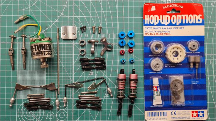
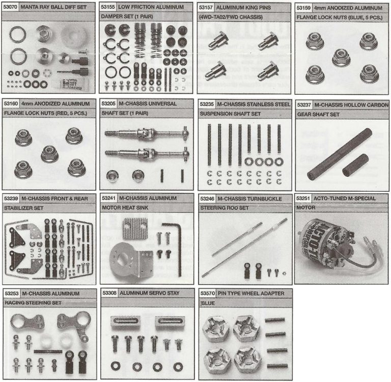
To build a chassis equipped with all the accessories to improve performance, fifteen accessories must first be sourced:
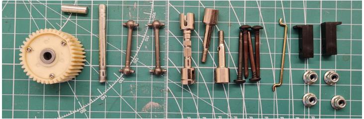
– 53070 described as “Manta Ray Ball Differential” – 53155 described as “Aluminium Dampers 4WD/FWD and Rally Car 2 pcs” – 53157 described as “Aluminium KingPin (4) TA02 / TA03 / FF-01 / M-01 Chassis, 4 pcs” – 53159 described as “4mm Anodized Aluminum Flange Lock Nuts (Blue)” – 53160 described as “4mm Anodized Aluminum Flange Lock Nuts (Red)” – 53205 described as “Drive shaft (2) M-01/ M-02 / M-03 / M-Chassis, 2 pcs” -53235 described as “M-Chassis Stainless Steel Suspension Shaft, 4 + 4 pcs” – 53237 described as “M-Chassis Hollow Carbon Gear Shaft Set”; follow the instructions to build it if this accessory is not available on the market – 53239 described as “M-Chassis Front and Rear Stabilizer” – 53241 described as “M-Chassis Aluminium Motor Sink” – 53246 described as “M-Chassis Turnbuckle Steering Rod Set” – 53251 described as “Acto Tuned M-Special Motor” – 53253 described as “M-Chassis Aluminium Racing Steering Set” – 53308 described as “Aluminium Servo Stay” 53570 described as “Clamp Type Alu. Wheel Hub 4mm, 4 pcs”
The accessories are shown in the image below starting from the top left corner going to the right and downward.
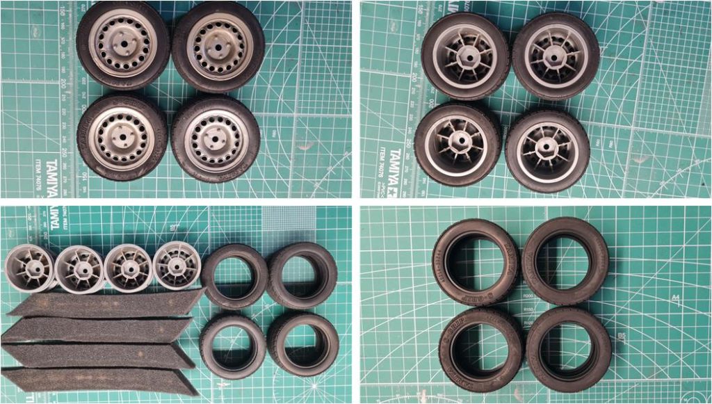
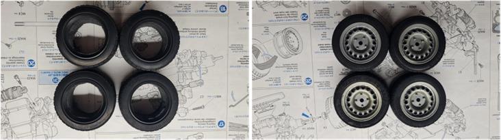
First, inspect and then refurbish the tires with the rims; check if the tires show any cuts on the tread or sidewall caused by impact damage. Look for any deformations on the rims due to impact. From the images below in the first row, it can be seen that both tires and rims are in perfect condition. Remove the tires from the rims, separate the internal reinforcement (image on the left in the second row) and wash both tires and rims with warm water (image on the right in the second row).
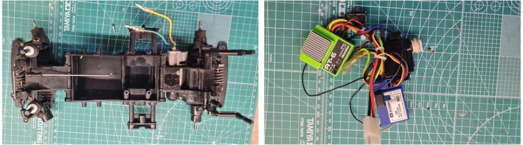
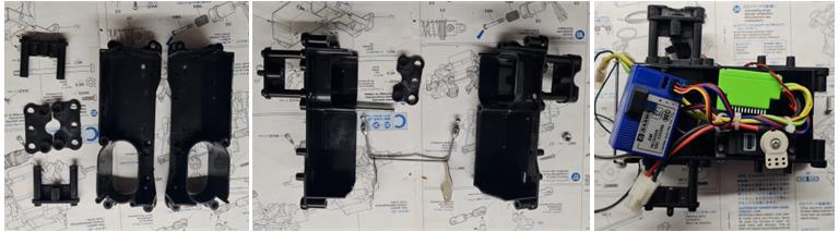
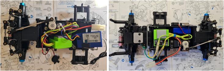
Separate the chassis (on the left in the image below) from the electronics (on the right in the image below). The receiver and speed controller are attached to the chassis plastic using double-sided adhesive, which can be removed by wiping with an alcohol-soaked cloth. The steering servo is mounted to the chassis using two plastic towers (standard components included in the factory setup).
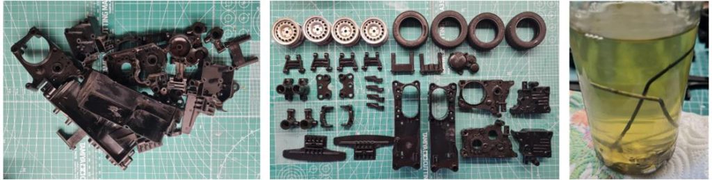
Disassemble the chassis to separate all parts and check for any broken or damaged components. Clean:
– all plastic components with warm water and soap (image on the left) – all gears with a degreaser – all metal small parts with a diesel bath (image on the right)
All plastic and rubber parts have now returned to almost new condition (center image), except for the lower part of the chassis, which still shows marks from road surface impacts.
By using a polishing compound, it’s possible to reduce the marks left by debris on the underside of the chassis; in this case, sanding the surface is not necessary. The marks are minimal and sandpaper might actually worsen the situation. Additionally, the decision to avoid sandpaper is due to the fact that the lower part of the chassis has a wavy shape reinforced with ribs, making it difficult to work the surface evenly. The main issue is the risk of wearing down the protruding areas more than the recessed ones.
Tamiya offers three compounds, each with different abrasive actions that result in different surface finishes:
– item number 87068; coarse abrasive compound that removes deeper marks – item number 87069; fine abrasive compound that smooths out the surface – item number 87070; polishing compound
Below in the image, the three sections making up the central part of the chassis are shown. This is the result after treatment.
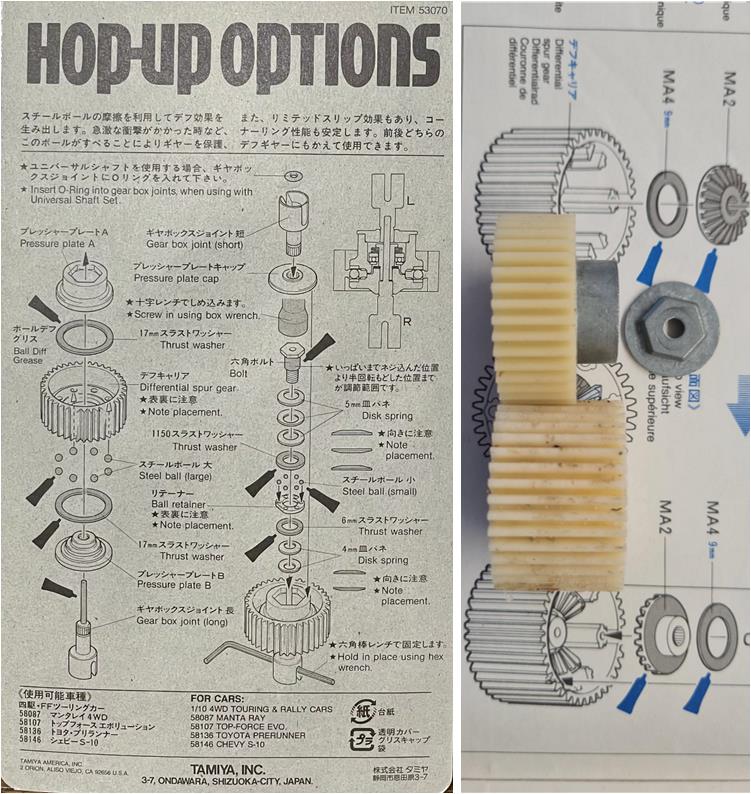
The plastic parts have been washed, the metal components treated with diesel, the tires degreased using kitchen soap in warm water and some plastic pieces polished… now begins the chassis assembly. First, install set 53070, the accessory described as “Manta Ray Ball Differential.” The ball differential (in the image it’s the top gear) is narrower than the standard model (in the image it’s the bottom gear), but it is perfectly suitable for use with M-01 and M-02 chassis.
Assemble the rear gearbox that includes the ball differential. Connected to the gearbox are the arms of the independent suspension system with a single central shock absorber. This gearbox must house the following components:
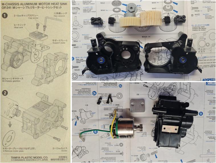
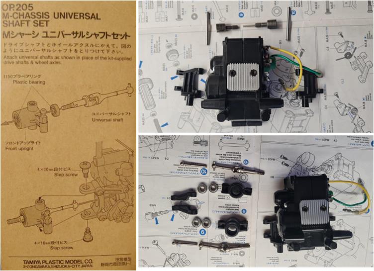
– set number 53237 described as “M-Chassis Hollow Carbon Gear Shaft Set” – set number 53241 described as “M-Chassis Aluminium Motor Sink” (refer to the manual in the image on the bottom left of the first row) – set number 53251 described as “Acto Tuned M-Special Motor” – set number 53205 described as “Drive shaft (2) M-01/ M-02 / M-03 / M-Chassis” (refer to the manual in the image on the bottom left of the second row), 2 pcs – four stainless steel pins from set 53235 described as “M-Chassis Stainless Steel Suspension Shaft, 4 + 4 pcs”
This completes the rear section of the chassis.
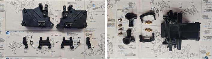
Assemble the front gearbox that includes the steering system and independent suspension with a single central shock absorber. Install the last four stainless steel pins from set 53235 described as “M-Chassis Stainless Steel Suspension Shaft, 4 + 4 pcs.” Install the lightweight kingpins for the steering knuckles from set 53157 described as “Aluminium KingPin (4) TA02 / TA03 / FF-01 / M-01 Chassis, 4 pcs.”
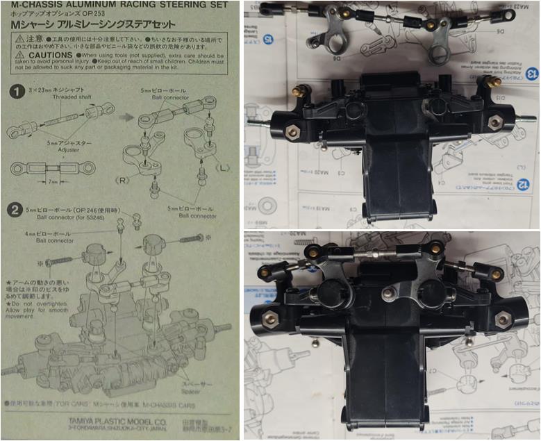
The lever steering system of the M-01 and M-02 chassis is known to have a certain amount of play that increases with use; for this reason, Tamiya released accessory 53253 described as “M-Chassis Aluminium Racing Steering Set.” Refer to the manual in the image on the bottom left. This completes the front section of the chassis.
Assemble the front and rear single shock absorbers from set number 53155 described as “Aluminium Dampers 4WD/FWD and Rally Car 2 pcs” (image on the left). Complete the four axles by inserting the aluminum hexagonal pin from set number 53570 described as “Clamp Type Alu. Wheel Hub 4mm, 4 pcs” (image on the right).
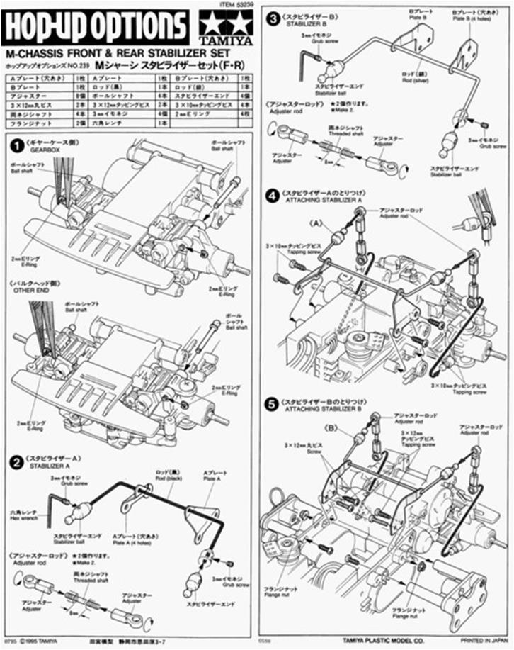
Assemble the central section of the chassis, which houses the electronics and battery. To this section, attach the rear anti-roll bar included in set number 53239 described as “M-Chassis Front and Rear Stabilizer.” Follow the instructions in the set manual.
The rear anti-roll bar has metal support plates installed inside the chassis shell. Once the two half-shells are assembled, it becomes difficult to screw in the four screws. Install the anti-roll bar before the two half-shells are joined together. Once the plastic tray is assembled, the electronics can be installed. For the steering servo, use the aluminum towers from set number 53308 described as “Aluminium Servo Stay.” Electronics include the electronic speed controller.
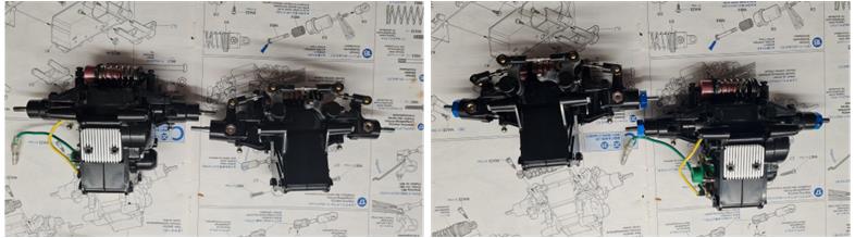
The three main sections are ready: central chassis, front assembly with suspension and steering system, rear assembly with suspension and motor. Now it’s possible to join the three parts to form the complete final chassis. Install the front anti-roll bar from set number 53239 described as “M-Chassis Front and Rear Stabilizer.”
The next step is to assemble the rims, foam inserts and tires. The tires have an inner side and an outer side—the outer side displays the tire specifications in raised lettering.
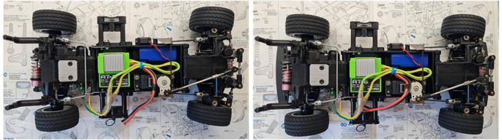
Mount the four tires and the two front and rear bumpers onto the chassis. The wheel nuts are red for the left side and blue for the right side. They correspond to sets 53159 described as “4mm Anodized Aluminum Flange Lock Nuts (Blue)” and 53160 described as “4mm Anodized Aluminum Flange Lock Nuts (Red).” The bumpers are identical to each other. In other M-02 chassis models, the front bumper differs from the rear one.
The original factory parts should be kept along with the completed model: satellite gear, plastic towers for the steering servo, two axles, two plus two joints, steering system pin, two plastic shock absorbers, plastic steering linkages…
Chassis rebuilt with the addition of all accessories to enhance performance.
Body restoration
The body is in perfect condition and no restoration work is necessary. Wipe with a damp kitchen paper towel to remove the superficial layer of dust.
Restored model with body
Images showing the finished model with body.
Chassis Update
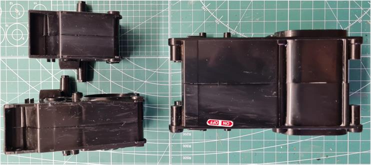
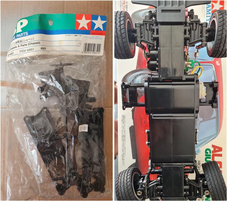
As of today (2025), sourcing new parts for the M chassis version 01 and 02 is not easy. Given the condition of the body (truly excellent), the central section was reserved for this chassis (right-hand image) when a 50651 set was successfully found. This set includes the two shells needed to build the central tub and the two shells for assembling the motorless section of the short chassis.
Tamiya, original figure, box art, guide book and catalogue are of TAMIYA INC, which does not endose or sponsor www.tamiyaclassic.com. Any brands, logos and trademarks represented on this website are the copyright of their respective owners.