Model
Tamiya TA03R TRF Special Chassis Kit, item number 58227, released in 1998 and available on the market until 2000.
Body absent because it is a chassis-only model.
TA03R TRF chassis, 257 mm wheelbase.
Analysis of the model to be restored
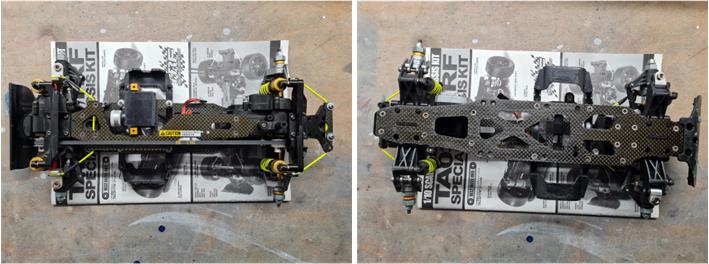
Tamiya models from the TRF series come equipped with numerous accessories to enhance performance. Buyers of this family aim primarily for track use, often further modifying the basic equipment to gain a performance advantage. As a result, the models available for sale are usually heavily worn and customized. An initial visual inspection, analyzing both the top and bottom views, allows assessment of the chassis condition; the upper side (left in the image below) is in excellent condition, while the underside (right in the image below) shows some scraping marks from contact with the road surface. Completing the model are the assembly instructions and the box. The instructions are in excellent condition, while the box shows tape, various damage and cuts.
The purpose of this restoration is to regenerate worn parts, replace broken ones, substitute non-original components and complete the chassis with only the accessories provided by Tamiya in the instruction manual. Restoring the chassis does not mean replacing all worn parts; everything that is intact is preserved, ensuring that the model’s operation is not compromised: the model must be ready to run with parts in perfect maintenance condition, even if used.
The chassis is equipped with all the accessories included in the basic kit, some of which are not externally visible; however, they are present:
– Code 53056 described as “Pin Type Wheel Adapter”,
– Code 58172 described as “TA-03 Universal Drive Shaft 1 pair”, with gold-anodized collar,
– Code 53200 described as “4WD Front One-Way Differential Unit”,
– Code 53357 described as “TA-03 Aluminium Motor Plate” anodized in gold,
– Code 50473 described as “RC Hi-Torque Servo Saver”,
– Code 53266 described as “TA03 Stainless Steel Suspension Shaft Set”.
Other accessories are visible in the images below:
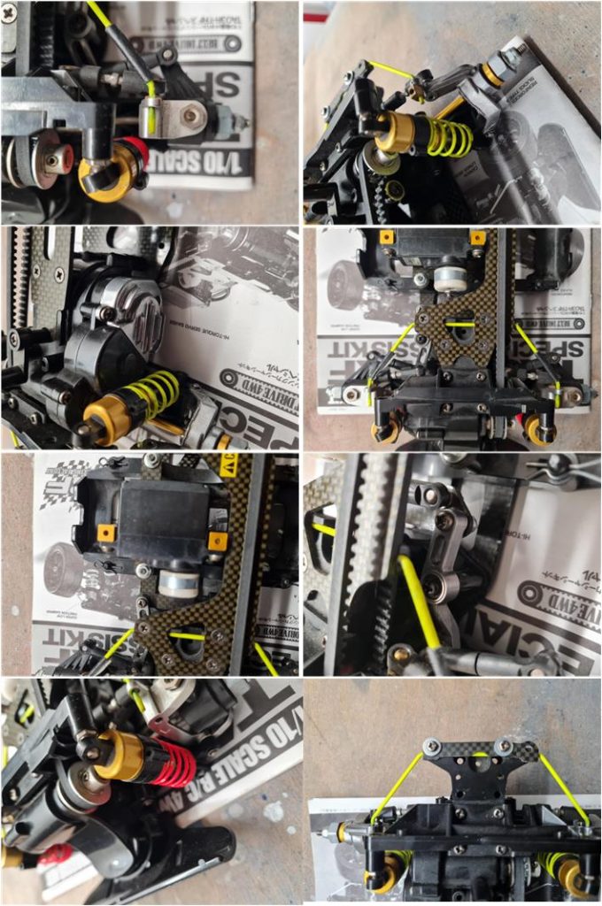
– Code 53276 described as “TA-03 Fluorescent Stabilizer Set”, modified with adhesive tape on the front (image left, first row) and with a stop at the rear (image right, first row),
– Code 53316 described as “TA-03 Aluminium Front Hub Carrier 1 pair” (image left, first row),
– Code 53288 described as “TA-03 Aluminium Rear Upright” (image right, first row),
– Code 53364 described as “TA-03R Carbon Steering Bar”,
– Code 53363 described as “TA-03R Carbon Chassis Set”,
– Code 53275 described as “TA-03 Aluminium Motor Heat Sink” (image left, second row),
– Code 53326 described as “TA-03 Aluminium Racing Steering Set” (image right, third row),
– Code 53308 described as “Aluminium Servo Stay” anodized in gold (image left, third row),
– Two 15-tooth aluminium belt pulleys (code 53291),
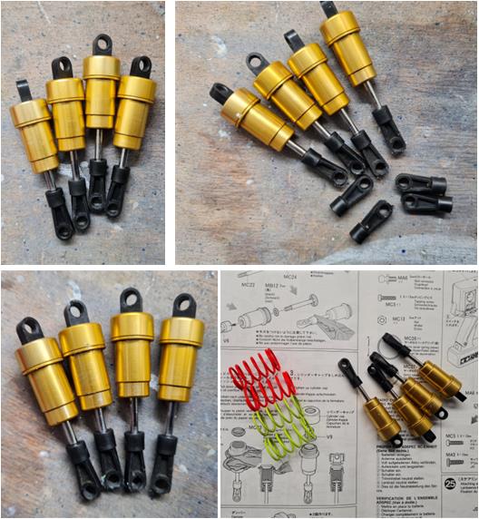
– Code 53280 low-friction alloy dampers anodized in gold with red springs at the front and yellow springs at the rear,
– Code 53312 described as “TA03 Carbon Stabilizer Support” (image right, last row).
Missing parts include rims, tires, receiver, motor control electronics and the electric motor. These components must be sourced from the market to complete the regeneration work.
There are two additional accessories compared to the factory equipment, installed to enhance performance; these accessories are listed in the manual and will therefore be retained after the chassis overhaul:
– Code 53304 described as “TA03R Urethane Bumper Set”, which is separate and not installed on the chassis,
– Code 53192 described as “4WD/FWD Upper Arm”.
Chassis Restoration
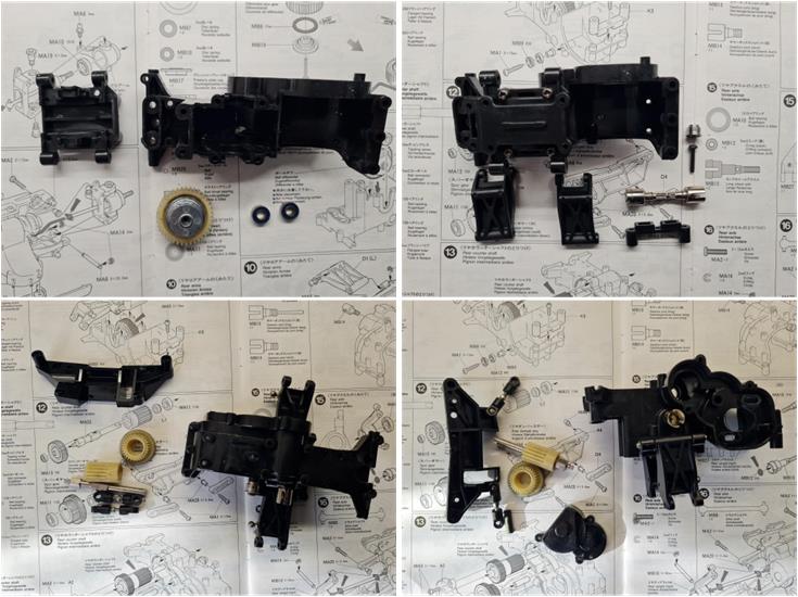
To begin the restoration, disassemble the model to better analyze the individual small hidden parts. The goal is to identify any issues not visible when the model is assembled, such as cracks or hidden breaks, modified, non-original, or missing components. First, separate the model into its three main subassemblies:
– Central part of the chassis consisting of the upper and lower carbon plates, carbon plate for the steering servo mount, battery subframe, double-lever aluminum steering system with carbon plate,
– Front gearbox housing in black plastic complete with differential, bumper and suspension system,
– Rear gearbox housing in black plastic complete with differential, suspension system and electric motor.
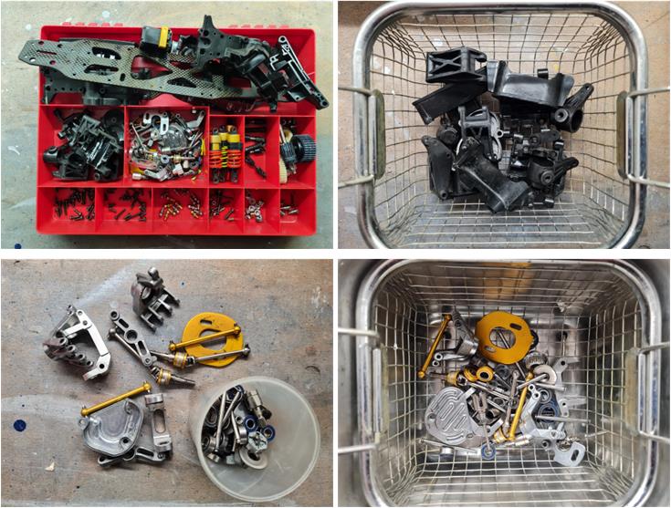
Next, proceed to disassemble the three subassemblies into their individual components to inspect them one by one. In the image below, all parts have been disassembled and sorted by material: carbon fiber, plastic and metal. Before starting any regeneration treatment, wash all parts (carbon, plastic and metal) with warm water and kitchen soap to degrease the surfaces. Use a toothbrush to reach the most hidden areas.
After these preparatory activities, the plastic and metal parts are ready to be treated with the ultrasonic cleaner, which will restore them to a like-new condition. The treatment times vary depending on the material:
– Plastic parts: treated for 30 minutes at 30°C
– Metal parts: treated for 45 minutes at 60°C
After washing in the ultrasonic cleaner, it is time to evaluate the parts to be used for rebuilding the chassis. Each individual component must be carefully assessed to decide whether it should be replaced; some parts may not be broken but may be worn to the point of being unsuitable for installation on the renewed chassis.
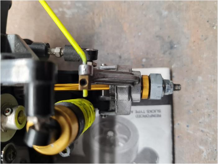
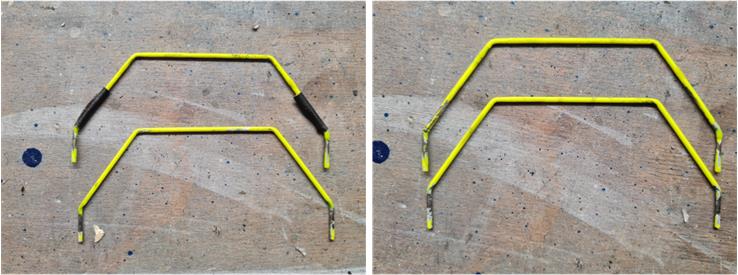
For the metal parts, only the two torsion bars require further analysis. The front and rear torsion bars are powder-coated in yellow. Both bars show several damaged areas where the paint has flaked off. The main cause is friction between the torsion bar and the hubs. In the case of the front-mounted bar, the adhesive from the insulating tape used as protection tore away the yellow paint (image on the left). The parts should be treated with a cloth soaked in alcohol. The alcohol removes the glue and dirt residue, but the bar remains without yellow paint in the areas where the coating has come off (image on the right).
The condition of the two anti-roll bars is not optimal, but they can still be used to restore this chassis to factory condition because they retain their original shape.
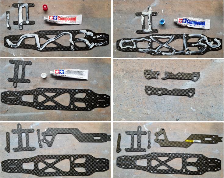
Before deciding whether to keep or replace the carbon parts, the plates were restored using a typical procedure for fiber components. Treating the surfaces of the carbon plates with abrasive paste for polishing has two objectives: reducing the depth of scratches and making the surfaces glossy. Tamiya provides three different treatments that vary in paste grain size. Apply these products in order:
– 87068 “Coarse”: the largest grain size, used to work the edges of deeper lines (first row, left image),
– 87069 “Fine”: the medium grain size, which removes the marks left by the coarse paste (first row, right image),
– 87070 “Finish”: the finest grain size, which makes the surface glossy (second row, left image).
Image sequence summarizing the procedure for working fiber surfaces:
– Apply the paste to the surface to be treated,
– Using a polishing cloth, apply circular motion until the paste disappears,
– Repeat this operation at least two or three times.
If the part shows many deep cuts, a hobby drill with a polishing accessory (cloth disc) can be used. The cloth disc has a stronger action compared to any manual polishing with a cloth. During polishing, the rear plate for the anti-roll bar broke; it had already been repaired with cyanoacrylate by the previous owner. This part was replaced with a new one, code 53312 described as “TA03 Carbon Stabilizer Support” (second row, right image). After the process (last row), the results of the abrasive paste treatment can be evaluated:
– The rear plate for the anti-roll bar is new.
– The steering plate, the subframe plate for the steering servo and the upper chassis plate have returned to a condition equivalent to new.
– The lower chassis plate, in the section most in contact with the road surface, still shows several scratches even after treatment. This is the area most affected by track use. The scratches were only slightly reduced in depth by the combined action of the three abrasive pastes. Furthermore, after completing the regeneration of the lower plate, it is evident that the front section bears the mark of a frontal impact that chipped the fiber.
Despite some negative points, the treatment has nonetheless restored the plates to a more than acceptable condition, consistent with the restoration objective of this model.
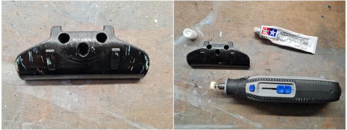
The same abrasive paste treatment applied to the fiber parts was also used on the front bumper in black plastic, which shows several marks in various colors ranging from white to red (left image). These are residues of colored plastic from objects the model collided with, leaving streaks on the black surface. A manual treatment alone cannot remove these marks, but they can be completely eliminated with the aid of a hobby drill and a cloth polishing disc (right image).
The low-friction gold alloy dampers are a special version released exclusively for the TA03 TRF family. The lower plastic ball joint is another part damaged by impacts with the ground (left image, first row). As of today (2025), plastic ball joints are also used in other models, making them easily available as spare parts (right image, first row). In the left image of the second row, the overhauled dampers are shown: the oil has been replaced and the internal rubber components have been changed. The springs are red at the front and yellow at the rear (right image, second row).
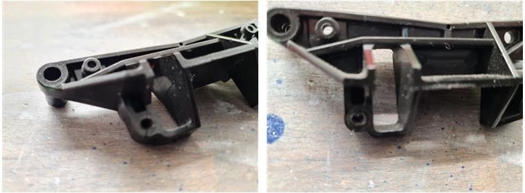
The rear shock tower is damaged at the point where the ball stud for the upper suspension arm is screwed in. Such damage cannot be detected from photos of the model; it can only be assessed after thoroughly cleaning each individual part. The rear tower must be replaced, even though it could still perform its function, because it is at risk of breaking.
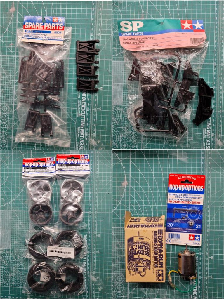
To achieve the best possible result, the most worn parts have been replaced with new equivalents. The model must have run on a track with very low ground clearance; it was already noted in previous steps that the underside of the carbon fiber chassis and the shock absorber joints were scratched. After washing the parts, it is evident that all four lower suspension arms also show significant wear. As of today (2025), the necessary replacements are available on the market. The black lower suspension arms are available in set 50701, described as part D for the TA03 chassis (left image, first row). The rear suspension tower is available in set 49110, described as part A (black) for the TA03 chassis (right image, first row).
To complete the list of parts needed to continue this restoration, four racing tires with four five-spoke black rims, code 53335 (left image, second row), must be sourced from the market; these are currently used on other models still in production (2025). The motor was not included in the kit, so the Dyna Run motor, code 53272, was selected along with a 21-tooth pinion gear with 0.4 module, code 53101. Both codes are listed among the accessories in the assembly instructions.
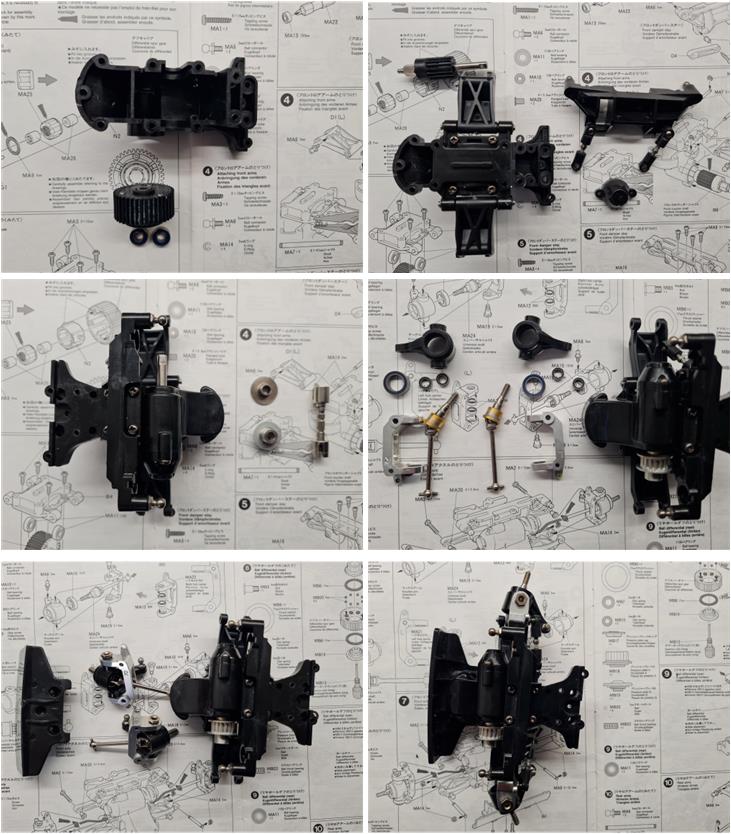
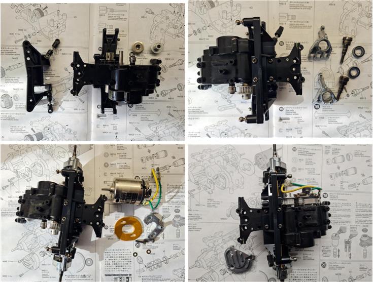
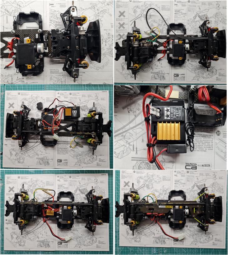
All parts are now ready to be assembled; the instructions begin construction from the front section, which includes the steering system, anti-roll bar, suspension and gears with the one-way differential.
The second section to be built is the rear part, which includes the electric motor system installed in the rear-central position, the anti-roll bar, the suspension and the gears.
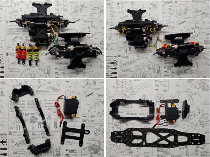
To complete the front and rear sections, it is sufficient to install the dampers with red springs at the front and yellow springs at the rear (first row). The construction of the final section begins by assembling the subframe that houses the battery (second row).
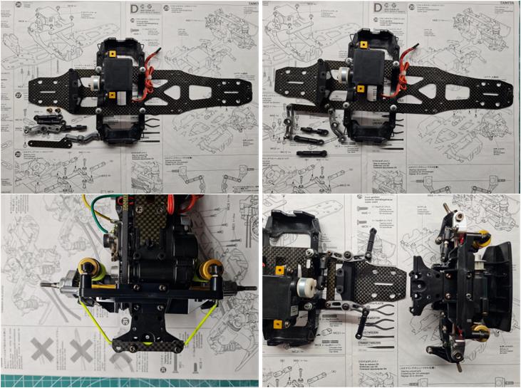
The battery subframe is installed on the lower carbon fiber plate. The central section is then completed by installing the steering system equipped with a double lever. The front section is the first to be joined with the central chassis, while the rear section is the second and final one to be joined with the central chassis.
By installing the rear section, the belt is also mounted, which does not require a tensioner since it is made of aramid. Now only the electronics are missing, consisting of a two-in-one unit (speed controller and receiver) CRP P160F, the steering servo and the wiring.
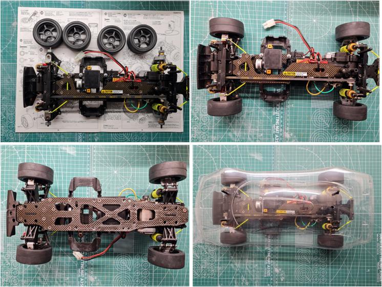
The tires have been mounted on the rims (left image, first row) and can now be placed on the chassis (top view, right image, first row; bottom view, left image, second row). To complete the chassis, it is sufficient to install the four towers that allow the body to fit onto the chassis. In the bottom right image, the Mercedes CLK–GTR body, code 50786, can be seen installed on the chassis.
Restored Model
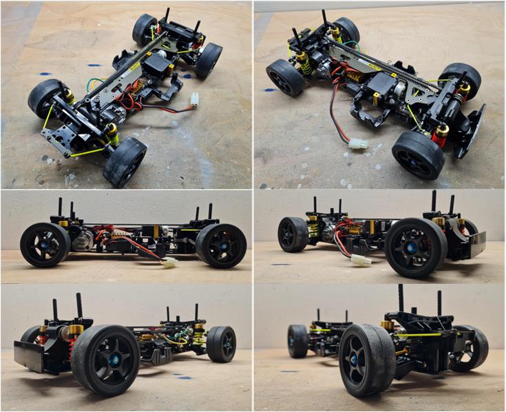
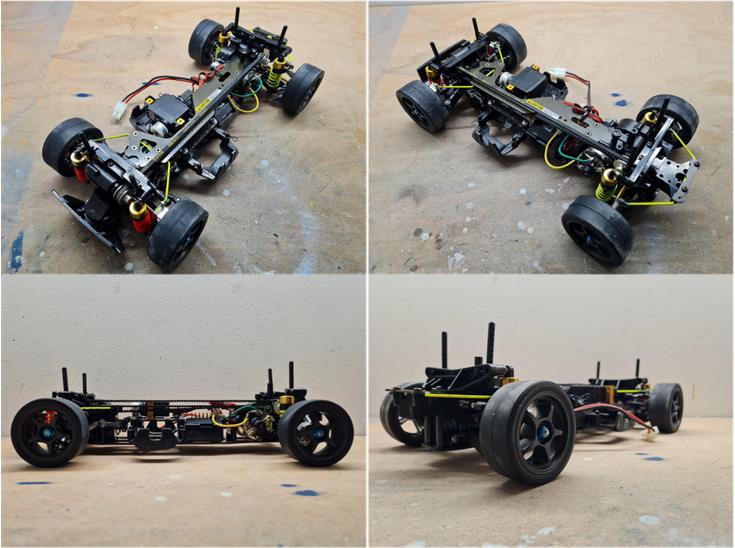
Images showing the completed model, bringing the chassis back to factory condition.