Tamiya Rover Mini Cooper, item number 58149, released in 1994 and available on the market until 2000. Lexan body M-01 front-wheel-drive chassis.
Analysis of the model to be restored
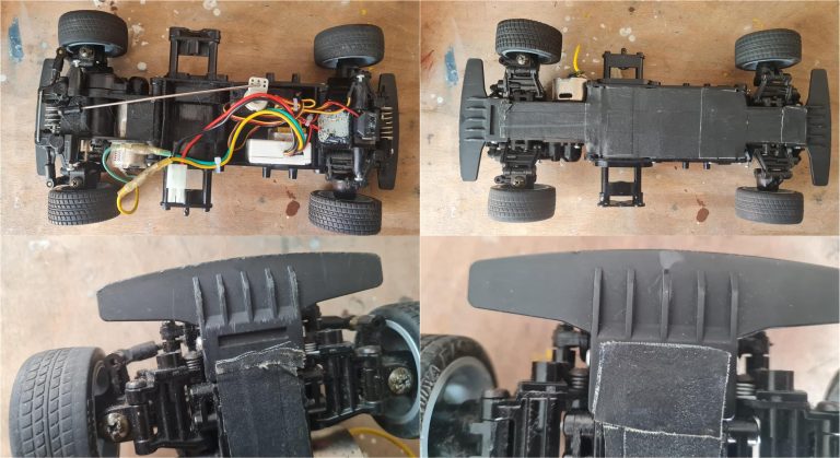
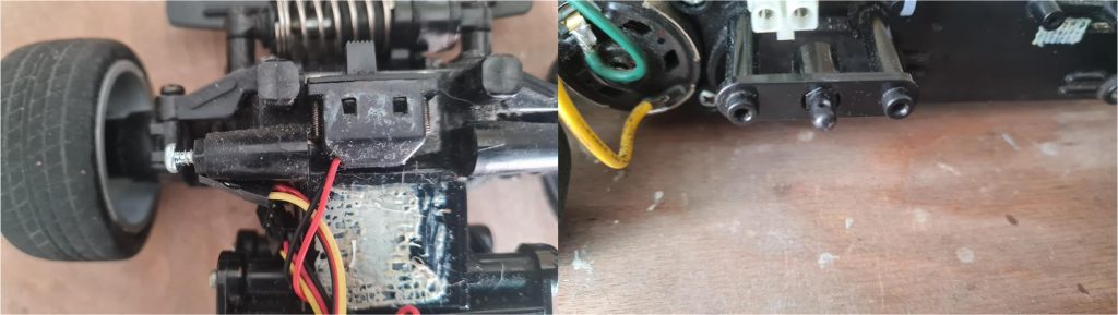
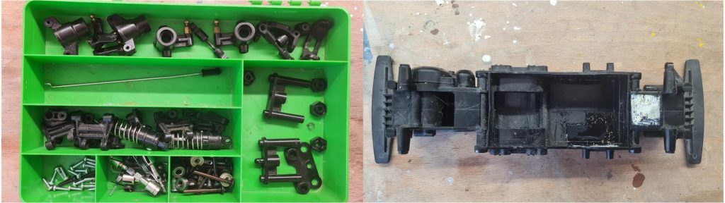
A top-down analysis of the model (top left image) reveals the presence of the electronic speed controller and the steering servo. The receiver is missing; in fact, the white double-sided tape on the rear section clearly shows where it was previously mounted. All parts appear to be present, but there are no visible performance-enhancing accessories. Motor, steering link, shock absorbers—all components are in order but correspond to the factory base configuration. The goal of this restoration is to achieve a model that matches the original factory specifications, so the current condition aligns with the project’s purpose.
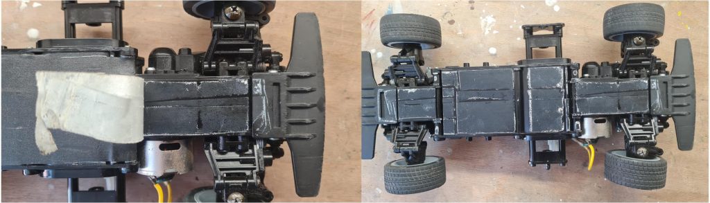
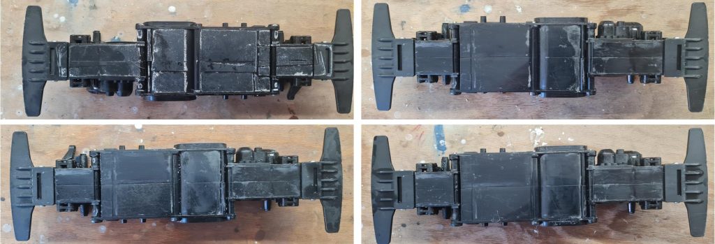
The underside view (top right image and the two bottom images) shows that the previous owner covered the entire bottom surface in contact with the asphalt using adhesive tape. This may be hiding scratches or damage, but further analysis cannot be performed until the tape is removed.
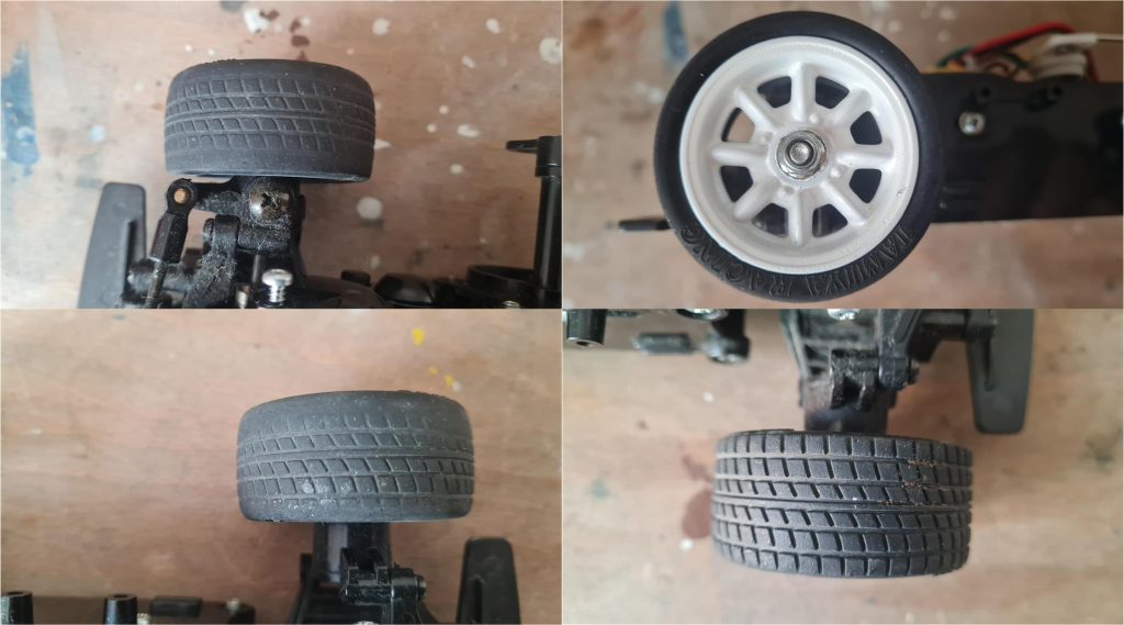
Analyzing the rims and wheels reveals that the model has been used for a considerable amount of time. The right-side wheels (images on the left) show worn tread on both edges, while the left-side wheels (second row image on the right) still have tread in perfect condition. It is likely that the wheels currently mounted on the left side were originally installed on the front axle. In typical use of a front-wheel-drive model, the front wheels are the ones that wear out the fastest. The rear wheels, on the other hand, are not subjected to significant stress and therefore their tread does not wear as quickly as the front ones. In any case, all four tires need to be replaced and it will also be necessary to consider replacing the rims, which have been painted white (image on the right in the first row).
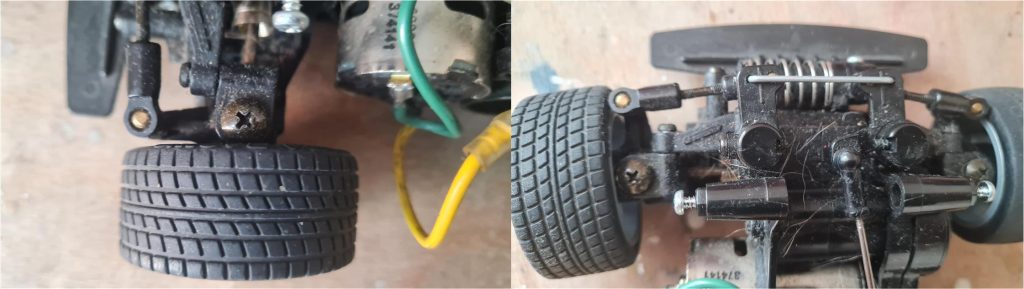
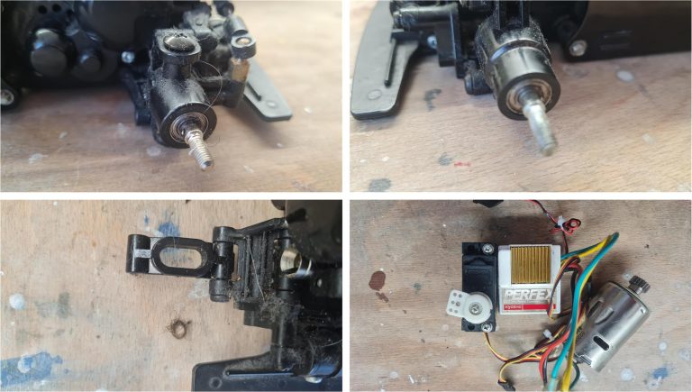
Close-up images of the suspension show that the lower arms are covered with a layer of dirt, lint and grease, confirming that the model has been used.
In the left image, the white double-sided tape that presumably held the receiver in place is clearly visible, while the right image shows that the battery retaining plate is missing. No visible damage is present, so in the first case it is sufficient to remove the tape, while in the second it is necessary to source the missing part.
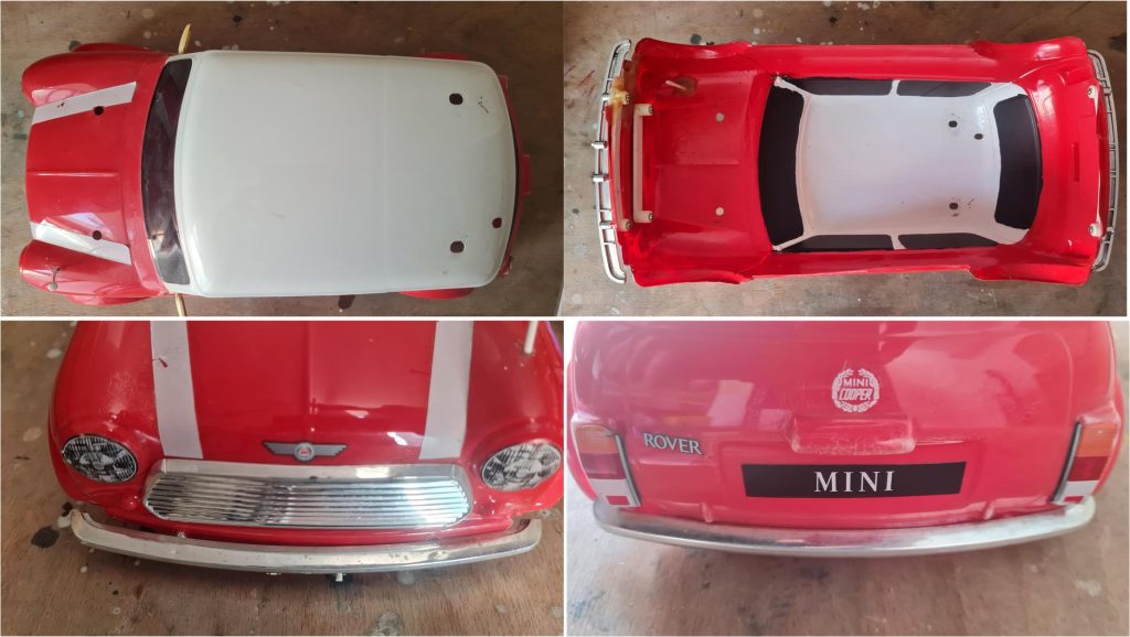
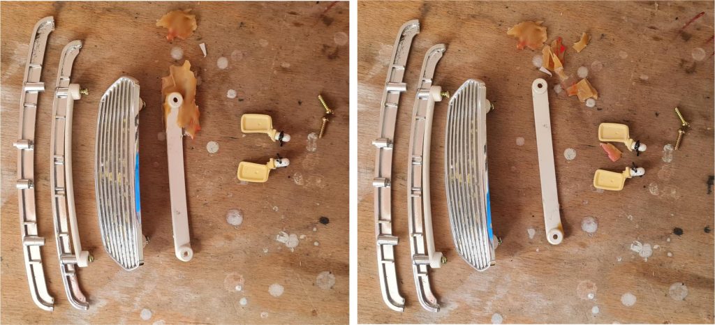
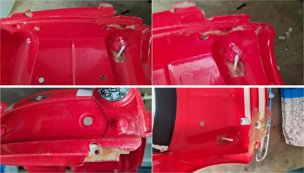
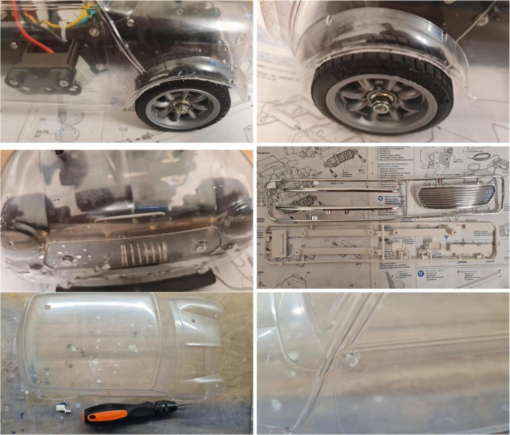
The body analysis shows that the color does not match the manual (red instead of green) and that some modifications have been made: installation of the radio antenna and a repair on the right side of the front section of the body (top right image). A hardened filler was used, which appears to lack flexibility—an unsuitable solution for a Lexan body. In the event of an impact, Lexan deforms and returns to its original shape; if a glue without similar elasticity is used, the first impact could cause a break. These areas need to be removed or revised, but the repair at the front bumper mount suggests a structural issue that may render the body unusable. All accessories are present: front grille (bottom left image), front bumper (bottom left image), rear bumper (bottom right image), right and left side mirrors (top left image).
Alongside the body and chassis, the instruction manual is present, intact and without any notable marks.
Chassis restoration
The first step is to investigate what lies beneath the adhesive tape. The previous owner used a high-quality product with glue that has not dried out, making it easy to remove the tape. The glue has remained attached to the underside of the chassis (right image), so this area must be cleaned with alcohol to remove the white residue. Once the tape is removed, it becomes clear that there is no damage to the underbody, no particular marks and both front bumpers are in perfect condition.
The residual glue is very adhesive and to remove it, a cloth soaked in alcohol must be used. To proceed, it is best to remove the wheels and suspension. Upon removing the wheels, the installation of a set of ball bearings becomes evident (first row images), which is surprising since there was no clear indication of performance-enhancing accessories. During disassembly, it is clear that the model was used on a surface with a high presence of lint, such as carpet (see tangle of fibers in the left image of the second row). The electronics and motor have been removed and set aside (right image, second row). It is only necessary to remove the double-sided tape that held the speed controller in place.
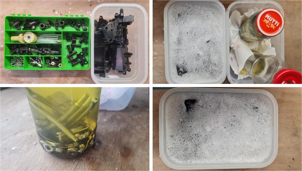
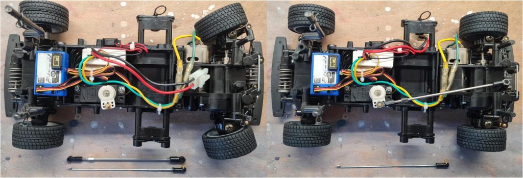
The plastic parts removed from the chassis have been neatly stored in a container awaiting cleaning (left image). Observing the chassis from above, it is clear that it is dirty near the front and rear suspension areas. Additionally, the double-sided tape that held the receiver and speed controller in place has left several residues.
The four images below show the effects of the alcohol treatment. Each time, a cloth is soaked in alcohol; the alcohol dissolves the glue, which is then absorbed by the cloth. Over time, the combined mechanical and chemical action transfers the glue from the chassis to the cloth. Periodically, the cloth must be cleaned or replaced.
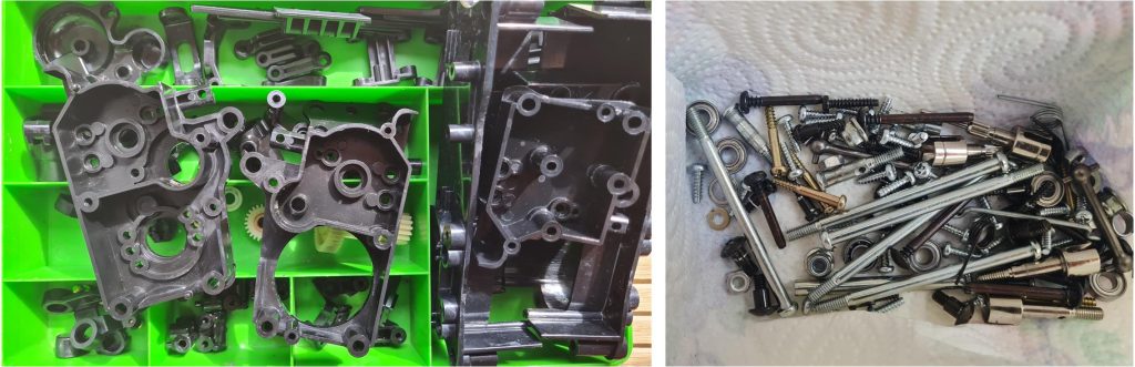
It is impossible to dissolve all the glue with this method, so further steps are necessary. Disassemble all chassis components, separating metal parts from plastic ones (top left image). Treat the plastic parts with hot water and generous use of kitchen soap (bottom right image). The soap dissolves the glue residue, which must be removed during rinsing and drying with a paper towel. Treat the metal parts with diesel fuel; a one-week soak removes all forms of rust and oxidation (bottom left image).
Mi dispiace, al momento ho difficoltà a rispondere alle richieste. Riproviamoci tra un po’.
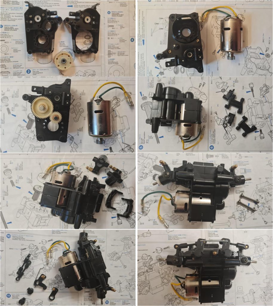
Assemble the front gearbox, which includes the motor, gears, steering system and single-shock suspension system. The hardware used follows the factory configuration, with metal pins, bushings and brass bearings.
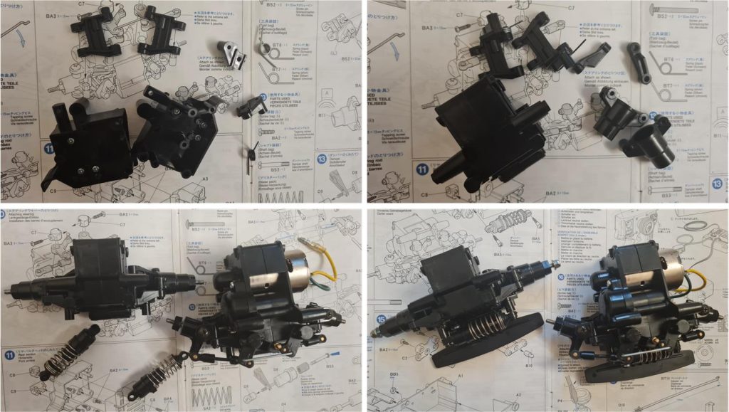
Assemble the rear gearbox (images in the first row), which includes only the single-shock suspension system. Once the front and rear sections have been assembled, the single shock absorber (left image in the second row) and the bumpers (right image in the second row) can be installed.
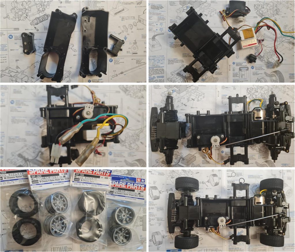
Assemble the central section that houses the electronics (images in the first row); this part is first joined with the front section (right image in the second row) and then with the rear section. The wheels were in poor condition with uneven wear and the rims had been painted white. The original sets for the M chassis are still available: the tires are item number 50560, described as “M-chassis radial tyres (2 pcs),” and the rims are item number 50569, described as “M-chassis 8 spoke wheels (2 pcs).” Once the electronics and the steering servo rod are connected, the chassis is complete.
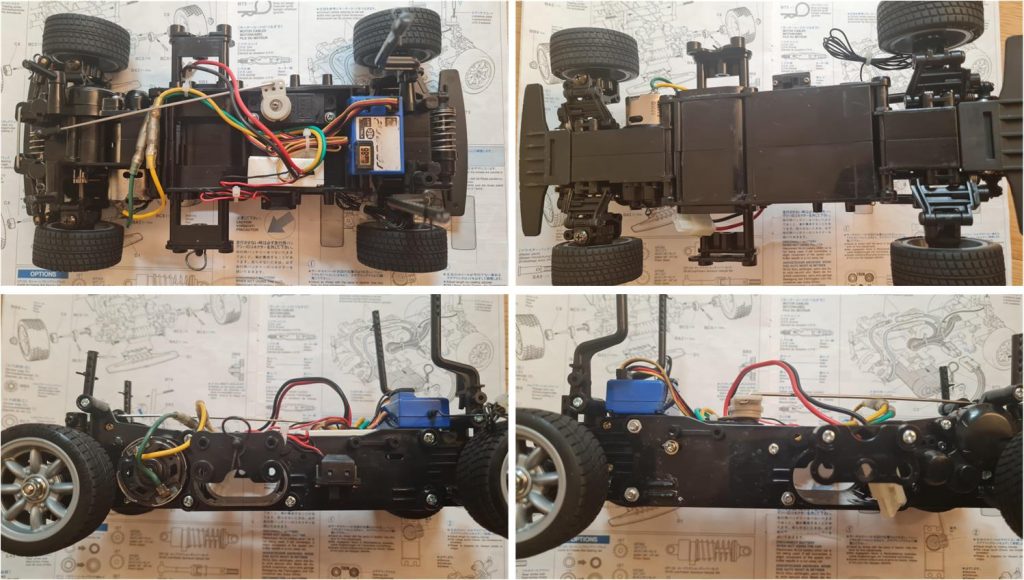
It is now possible to assess the final result; the chassis has returned to its original factory condition. The tape applied to the underside by the previous owner protected the chassis, which shows no scratches and appears as new.
The only performance-enhancing accessory is set 53246, described as “M-Chassis Turnbuckle Steering Rod Set.” The original rod is stored together with the instructions in case a return to the factory configuration is desired in the future. This accessory is inexpensive and allows for steering adjustment, which is why it is installed on many models equipped with the M-01 chassis. The chassis is now ready to be joined with the body.
Body restoration
The front grille, front bumper, rear bumper and both side mirrors are in perfect condition (left image). The filler used for the front bumper remained stuck to the internal mount, but it was easily removed by applying pressure with a finger (right image).
The body on the front right side has suffered an impact that caused a fracture extending to the headlight. The entire lower lip is missing. A repair may be possible, but this project will be addressed in a future restoration.
The original body is not up to the standard of the chassis, which is practically in factory-new condition. Therefore, the original body is set aside for future work and a new body set, item number 50567, is used. This set includes the Lexan body, decals and plastic parts to complete the chassis.
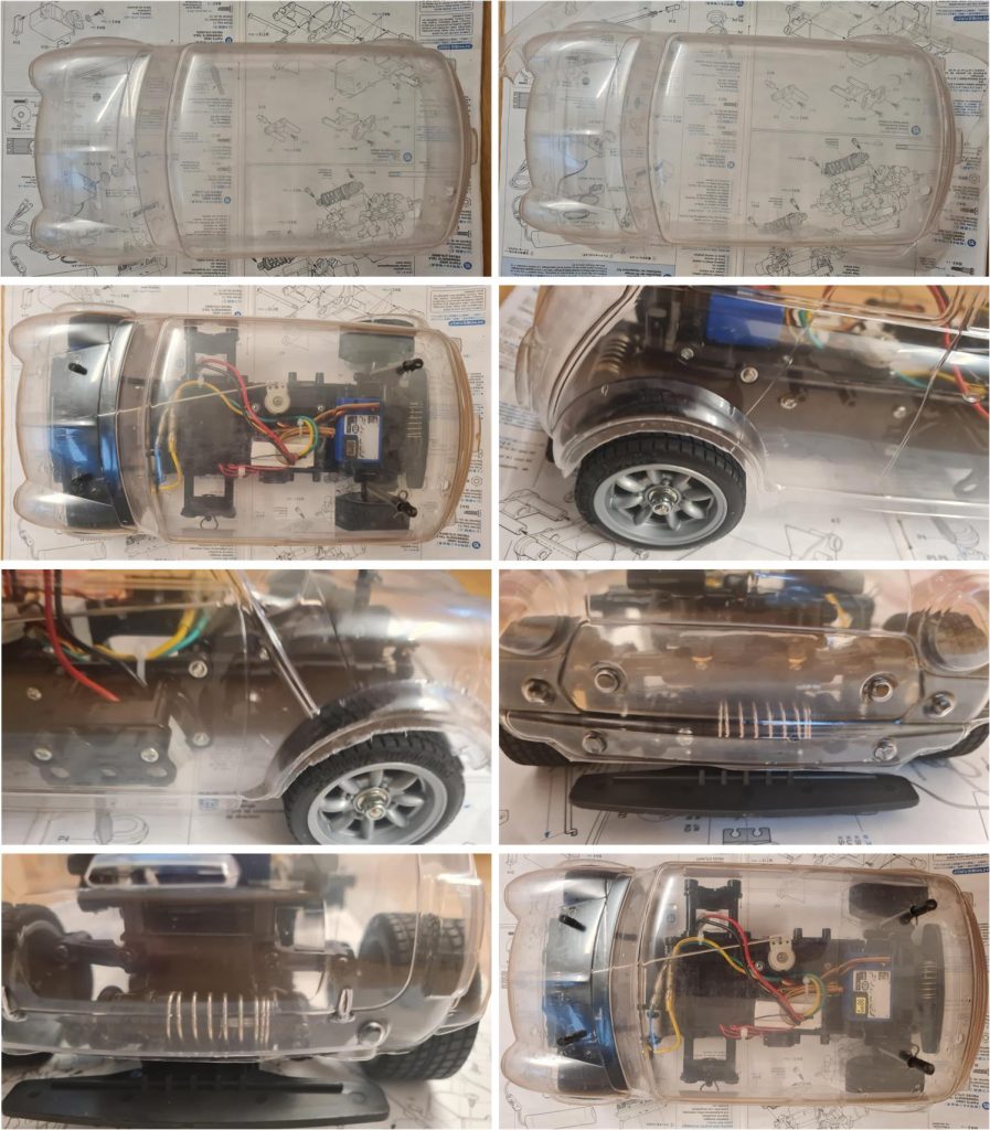
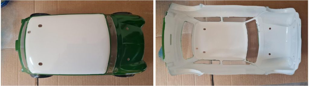
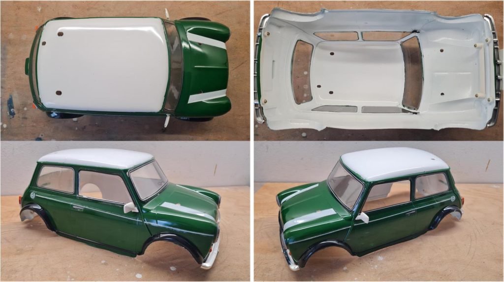
The first step is to wash the inside of the body with hot water and kitchen soap to remove any Lexan processing residue (left image in the first row). Lexan is lubricated with oils during molding, which prevent paint from adhering properly. Excess parts of the Lexan body must be trimmed; the cutting lines are indicated in the instruction manual and marked on the body with a thin line. Follow the line using short-blade scissors for curved sections and long-blade scissors for straight sections. To avoid cutting into the usable part of the body, it is best to stay well outside the line, leaving extra material (see images in the third row and the left image in the last row). Test the fit of the body on the chassis (right image in the last row).
Use curved files for rounded sections and flat files for straight edges to refine the cut line and remove excess material. A small hobby drill with abrasive bits can also be used. The holes for the four body posts and the antenna are already present on the body, while the two holes for the side mirrors are missing.
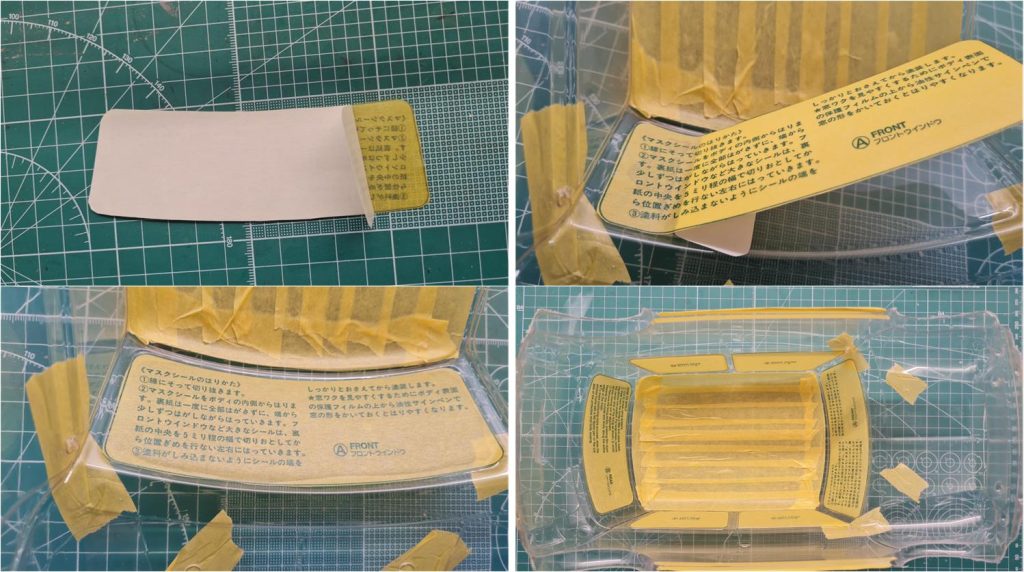
The color sequence for Lexan bodies goes from darkest to lightest. Read the guide on how to apply paint to transparent parts. Apply masking on the roof, which will be White PS1, on the holes for the body posts that connect the body to the chassis, on the holes for the side mirrors and on the windows and windshield. The window masks are included with the decals. Start by peeling off a tab of the protective film that covers the adhesive side of the mask (left image, first row), place the adhesive on the area to be masked so that the exposed part adheres to the body (right image, first row), completely remove the protective tab making sure the mask adheres properly (left image, second row) and apply all the provided masks (right image, second row).
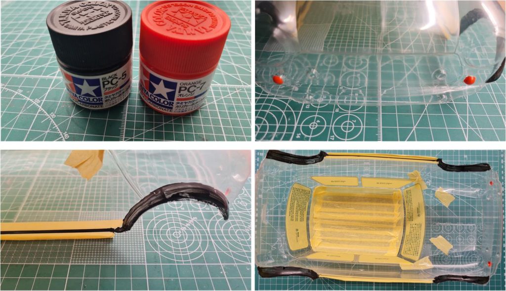
The colors for the wheel arches and front indicators are PC5 black and PC7 orange, respectively. These are Lexan-compatible paints to be applied with a brush, as the areas are too small for spray application.
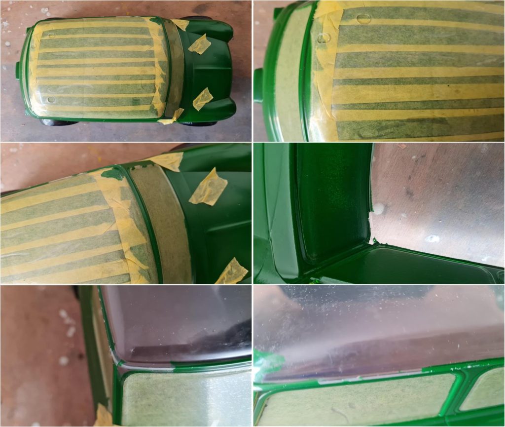
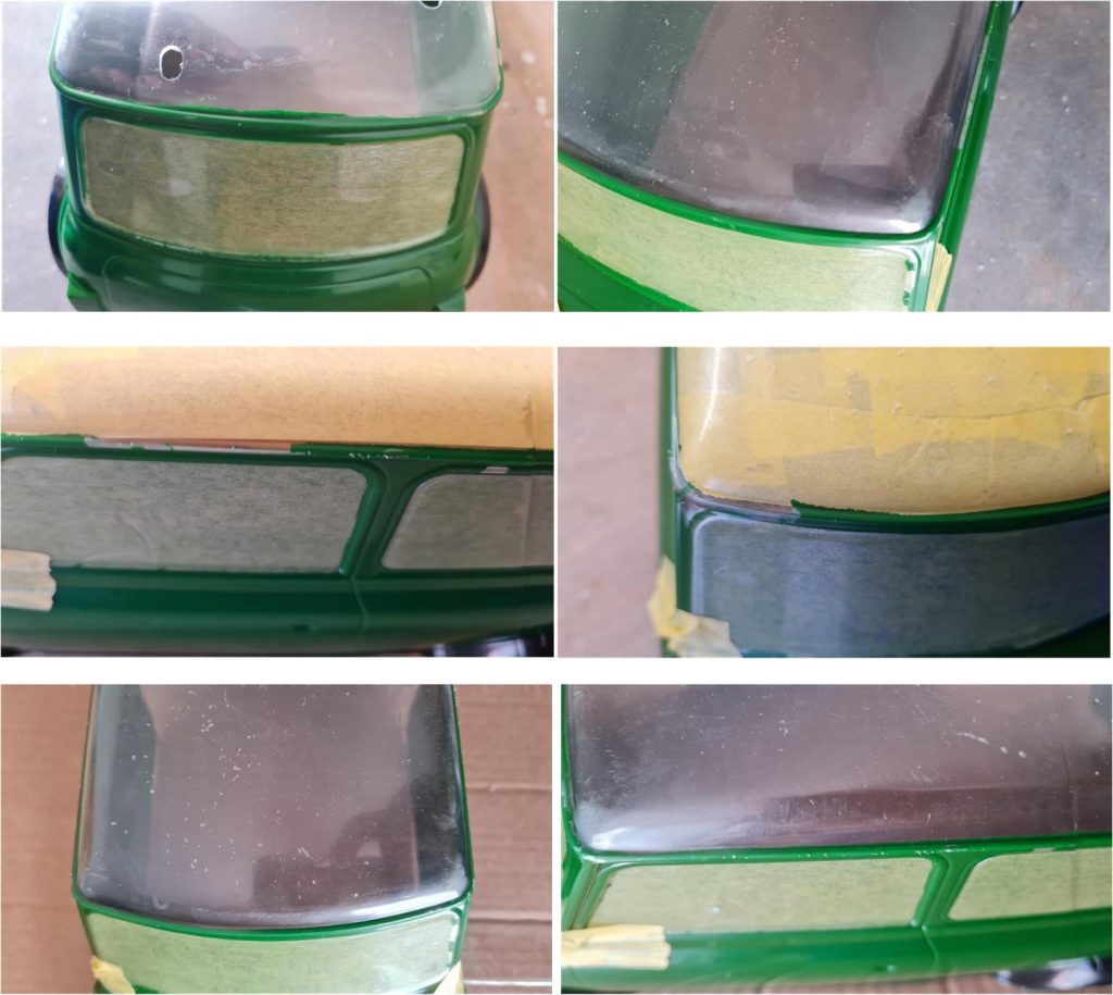
After applying the final coat of brush-painted colors to the wheel arches and indicators, wait 5–6 days to ensure the black and orange PC5 and PC7 paints are fully dry; otherwise, the solvents in the PS paints may damage them. Once the proper drying time has passed, apply PS9 green over the body, the masks and the areas painted with PC black and orange. Apply multiple coats of PS9 green; the first coat should be light, followed by heavier layers. During painting, something went wrong and the paint smudged on the front left corner of the roof (second row, left image) and the rear section (first row, right image). Additionally, the masking on the roof was removed too late—beyond the recommended 4-hour window—causing some paint to stick to the masking tape: on the front right corner (second row, right image and third row, right image) and above the driver’s door (third row, right image).
To correct the overspray, simply use a cotton swab soaked in alcohol and gently rub the excess paint until it comes off. Then clean the entire transparent surface with a damp kitchen towel to remove any remaining alcohol and dissolved paint (first row: left image shows the rear area, right image shows the front corner after cleaning). New masking has been applied to fix the missing paint above the driver’s door (second row, left image) and on the front left corner (second row, right image). New coats of PS22 paint must be applied (last row: left image for the front right corner, right image for the driver’s door).
It is necessary to wait until the green paint is completely dry and no longer susceptible to being dissolved by solvents; wait at least one week after the final green coat before applying the white paint. Apply the first coats of white sparingly and lightly. Do not use spray cans that are nearly empty for these initial coats, as the solvent tends to concentrate at the end of the can and can be aggressive enough to dissolve the previously applied paint.
Now it’s possible to apply the decals and add the body accessory parts: front bumper, engine grille, driver’s side mirror, passenger side mirror and rear bumper.
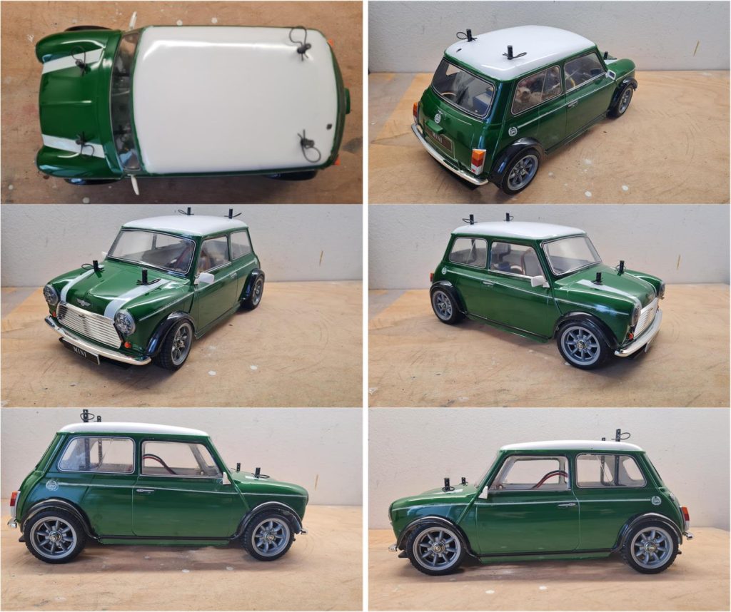
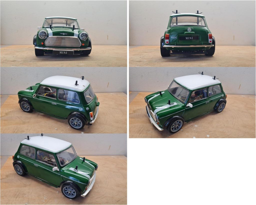
Restored model with body
Images showing the completed model with body.
Chassis update
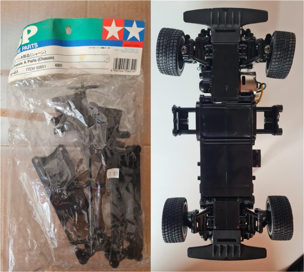
Today (2025) it is not easy to find new parts for the M chassis version 01 and 02. Given the condition of the body (new), the rear section was reserved for this chassis (image on the right) when it was possible to find a 50651 set. This set consists of two shells to build the central tub and two shells to build the motorless section for the short chassis (rear part for the M-01 chassis).
Tamiya, original figure, box art, guide book and catalogue are of TAMIYA INC, which does not endose or sponsor www.tamiyaclassic.com. Any brands, logos and trademarks represented on this website are the copyright of their respective owners.