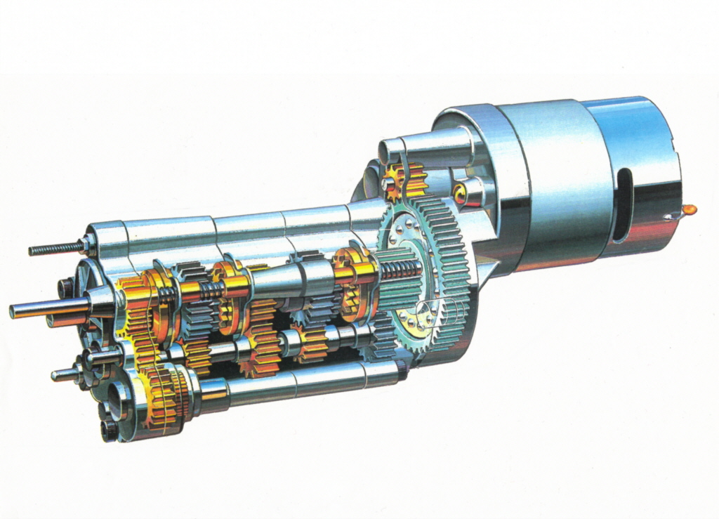
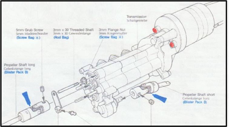
Tamiya releases for sale from 1982 to 1996 four models equipped with a 3-speed gearbox, installed on 1/10 scale radio-controlled models with 4WD-2WD:
– Toyota 4×4 Pickup, model number 58028, available on the market from 1982 to 1985; 3-Speed chassis – Blazing Blazer, model number 58029, available on the market from 1982 to 1984; 3-Speed chassis – Bruiser, model number 58048, available on the market from 1986 to 1992; Bruiserchassis – Mountaineer, model number 58111, available on the market from 1993 to 1996; Bruiser chassis
The gearbox undergoes only minor variations between the 3-Speed and the Bruiser chassis.
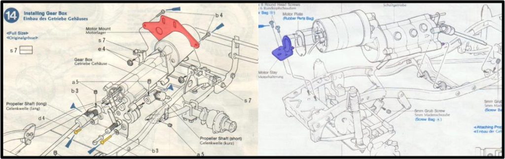
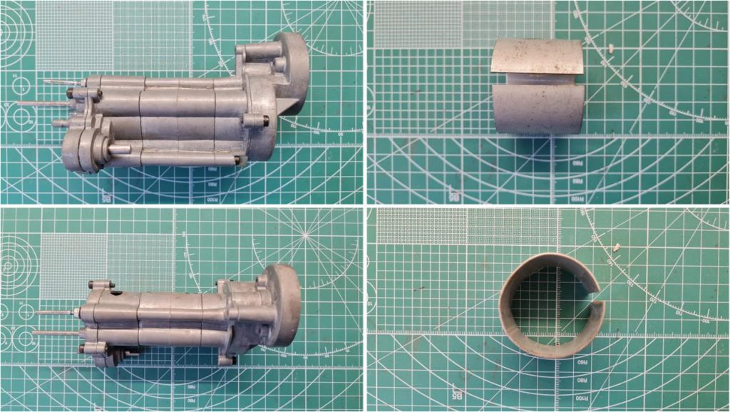
The main difference lies in the motor: a Mabuchi RS540 in the 3-Speed chassis and a Mabuchi RS750SH in the Bruiser chassis. The different motor explains the distinct type of plate used to secure the gearbox and motor system to the chassis at the front; the 3-Speed chassis plate is highlighted in red and the Bruiser chassis plate in blue. Another difference is in the system used to attach the gearbox and motor system to the chassis at the rear, where the 3-Speed chassis uses two 3 mm diameter hex screws, while the Bruiser chassis uses two pins integrated into the gearbox casting. In the image, the two screws of the 3-Speed chassis are highlighted in orange and the left pin of the Bruiser chassis in purple.
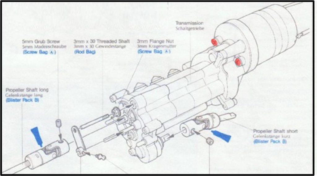
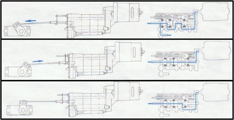
The two gearboxes are not interchangeable. However, the gears and functionality are exactly the same. It is possible to shift gears by acting on the rod located at the rear of the gearbox. The action can be manual or performed by a remotely controlled servo motor. When the rod is pushed out of the gearbox casing towards the rear, the low speed is selected, engaging traction on all four wheels.
When the rod is pushed inside the gearbox casing towards the front, the maximum speed is selected with only two driving wheels engaged.
When the rod is left in its resting position, the intermediate speed is selected, with only two driving wheels engaged.
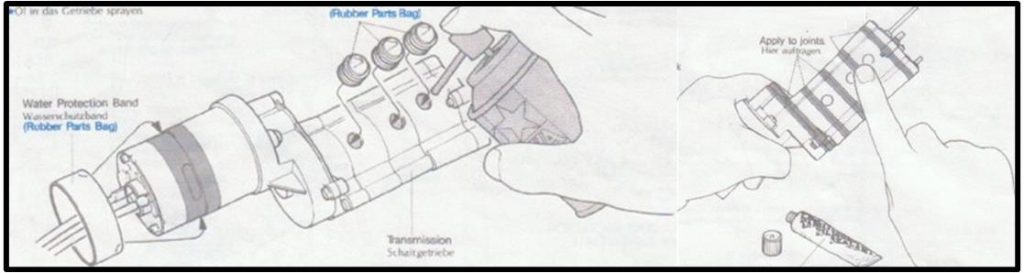
Each movement corresponds to a displacement of approximately 8–10 mm. The gearbox is preassembled in the factory; in the instructions for the four models, it is only suggested to apply a thin layer of silicone along the joints to prevent dust and water from entering.
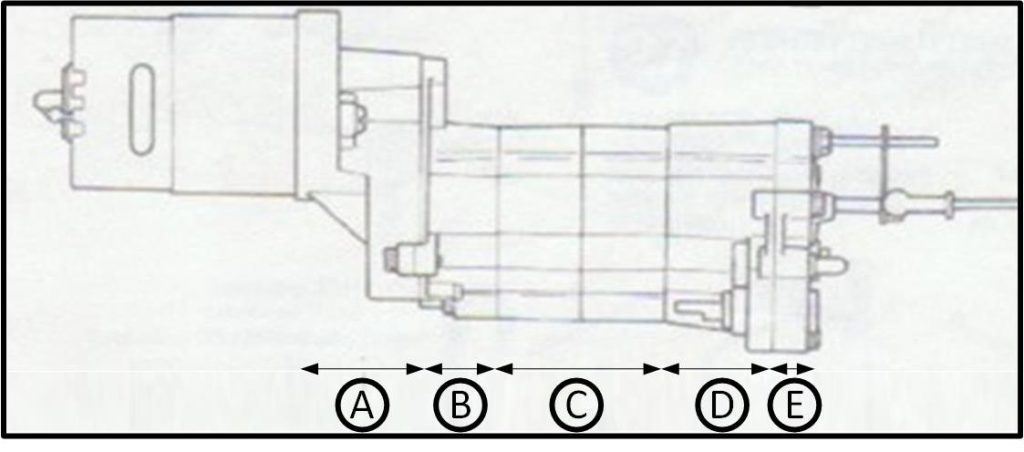
Disassembling to repair or restore a 3-speed gearbox is not a simple or intuitive operation. It is essential to be well-organized to gather every small part and avoid losing any pieces. Gears, springs, forks and shafts are all made exclusively for this gearbox; only the bushings are shared with other Tamiya models. Finding spare parts is challenging. The gearbox is divided into 5 sections, which Tamiya names starting from the front to the rear. Some notes:
– The motor is installed in section A, – Section C appears to consist of two separate sections, but it is actually a single casting, – The gear-shifting rod exits from section E.
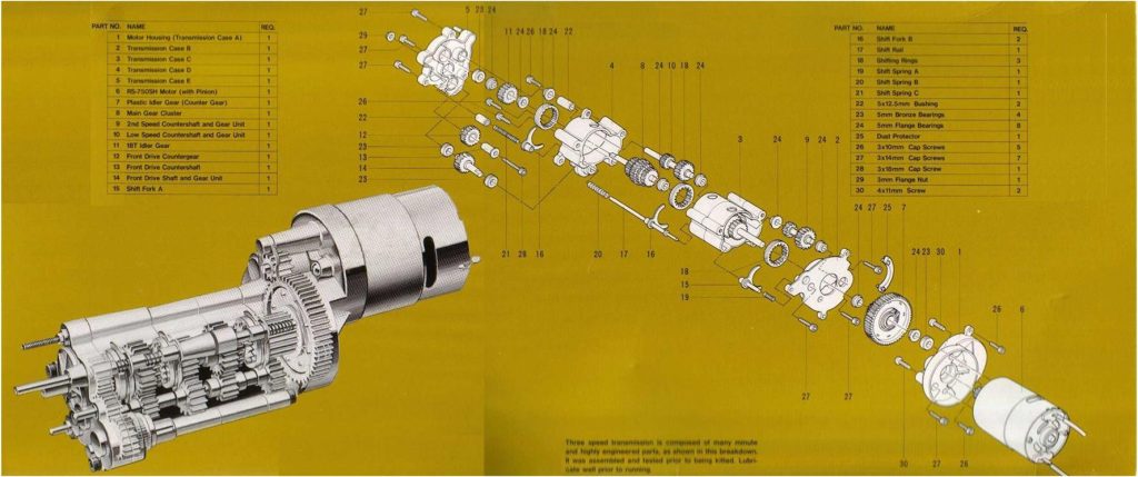
The image below represents an exploded view of the model, along with the bill of materials listing the names assigned by Tamiya to the individual parts. This nomenclature is also referenced in the manual below.
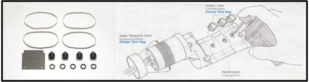
A gearbox awaiting disassembly features silicone strips applied to seal the gear casing, ensuring the lubricant remains inside and dirt stays outside. The three transmission oil holes are sealed with rubber caps, which, as of 2025, Tamiya offers under code 51499, described as “Rubber Parts Set A for Toyota 4×4 Pick-Up Bruiser.” Alternatively, rubber plugs or adhesive tape can be used to seal the three holes.
Disassembling a 3-speed gearbox
First, remove the three rubber caps, taking care not to damage them. Proceed to remove the silicone by mechanically detaching it piece by piece, ensuring not to scratch or damage the 5 metal casings. Once all traces of silicone have been removed, the motor can be detached from the gearbox assembly by unscrewing the two 4 x 11 mm screws, highlighted in red.
On the left, the gearbox is ready to be disassembled, while on the right, the engine heat sink serves as a perfect workbench for supporting the gearbox during operations.
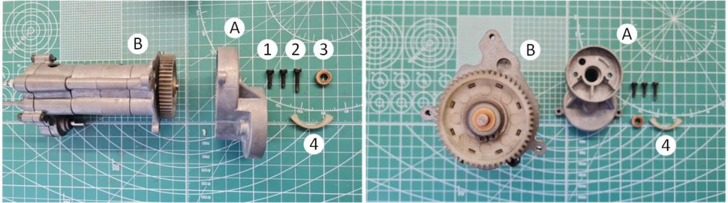
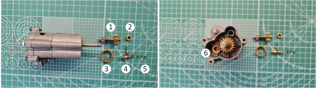
Unscrew the two 3 x 10 mm hex socket screws (marked as “1”) and the 3 x 15 mm hex socket screw (identified as “2”) that secure section A to the gearbox in section B. Now, section A can be removed, exposing the only plastic gear (referred to as “plastic idler gear, idler gear”) in the gearbox. Be mindful of the 1150-sized bushing (marked as “3”) installed in section A. The white crescent-shaped plastic component (identified as “4” and referred to as “duster protector”) serves as a dust shield for the lower part of the gearbox and also acts as a shock-absorbing element.
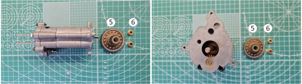
Remove the white plastic gear (identified as “5” and referred to as “plastic idler gear, counter gear”) along with the two 850-sized bushings (marked as “6”). The white plastic gear has the code 4265002.
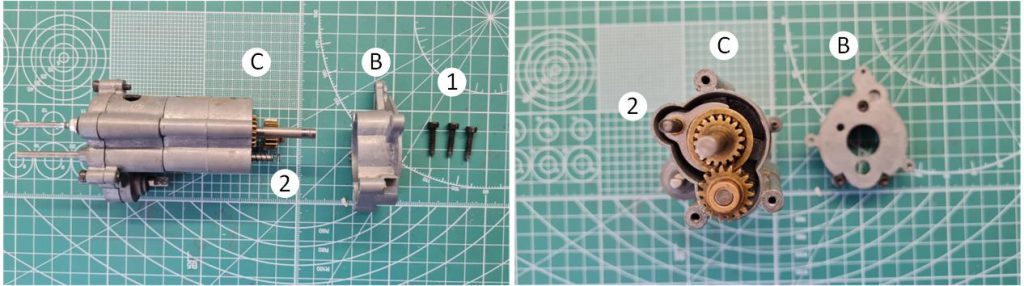
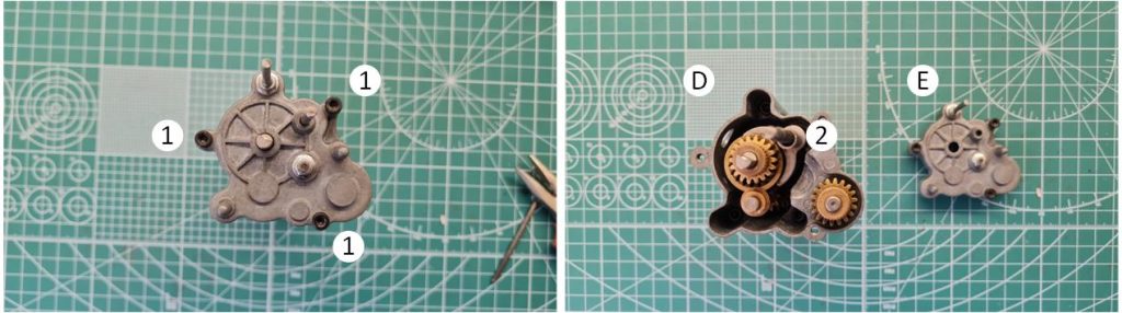
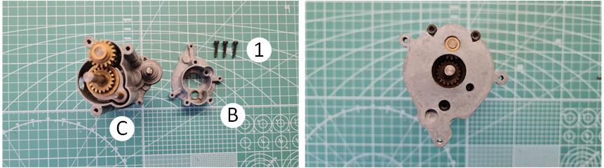
Unscrew the three 3 x 15 mm hex socket screws (identified as “1”) that secure section B to the gearbox in section C. Carefully remove section B, ensuring that the spring (marked as “2”) located between sections C and B is not lost.
From section C, extract:
– The gear selection system and separate the shift fork (identified as “4” and referred to as “shift fork A”), the toothed ring (marked as “3” and referred to as “shifting ring”) and the spring (identified as “5” and referred to as “shift spring A”). – The double-gear transmission shaft (designated as “2nd speed countershaft and gear unit”), identified as “1” and separate its two 850-sized bushings (marked as “2” and “6”). The bushing “6” is housed inside the gearbox casing and may require a mechanical action for extraction; see the image on the right.
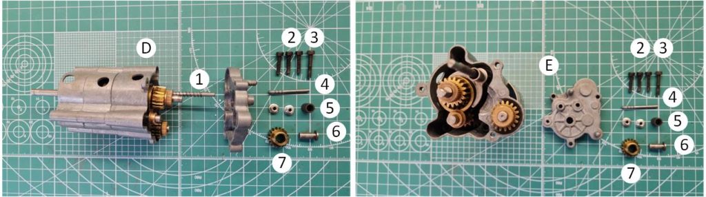
Rotate the gearbox to the side of section E, which is the rear part of the gearbox. Unscrew the three 3 x 15 mm hex socket screws (identified as “1”) that secure section E to the gearbox in section D. Extract section E carefully, ensuring the spring (marked as “2”) is not lost.
Before proceeding further, store the central part of the gearbox carefully to ensure no gears, springs, or bushings are lost. Focus on section E; inside, unscrew the 3 x 18 mm hex socket screw (identified as “3”) that secures the gear shaft (marked as “7”) to section E. Pay attention to the locknut installed on the outside of the gearbox. The 3 x 18 mm hex socket screw functions as a shaft for the flanged bushing (identified as “6” and referred to as “front driver countershaft”), the cylindrical plastic bushing (marked as “5”) and the gear (identified as “7” and referred to as “front driver gear”). Unscrew the pin (identified as “4”) and its nut from section E.
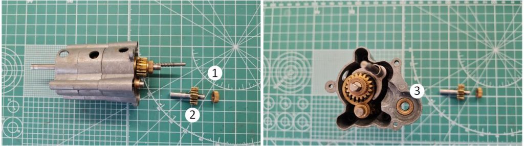
Extract the transmission shaft (identified as “2” and referred to as “front driver shaft and gear unit”) with its integrated gear and the 1150-sized bushing (marked as “1”). Be mindful of the 1150-sized bushing (identified as “3”), which is housed within the casing of section D.
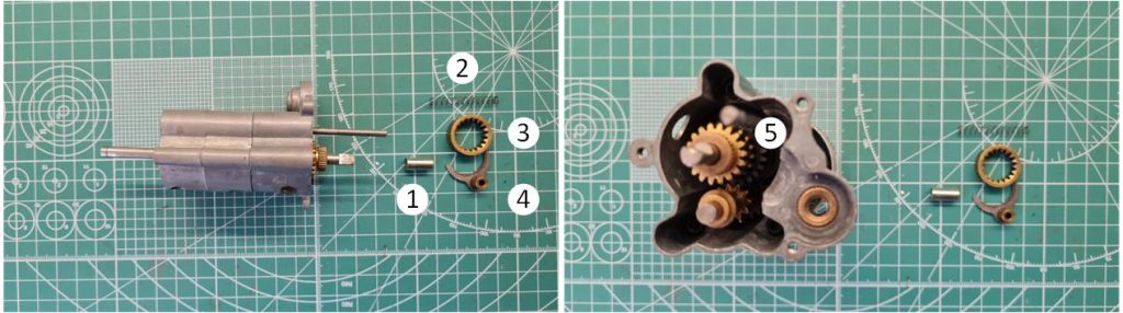
Extract the gear shift fork assembly, consisting of the 5 x 12.5 mm metal cylinder (identified as “1” and referred to as “5×12.5 mm bushing”), the spring (marked as “2” and referred to as “shift spring C”), the fork (identified as “4” and referred to as “shift fork B”) and the toothed ring (marked as “3” and referred to as “shift ring”). Pay close attention to the spring remaining on the gear selection shaft (identified as “5” and referred to as “shift spring B”).
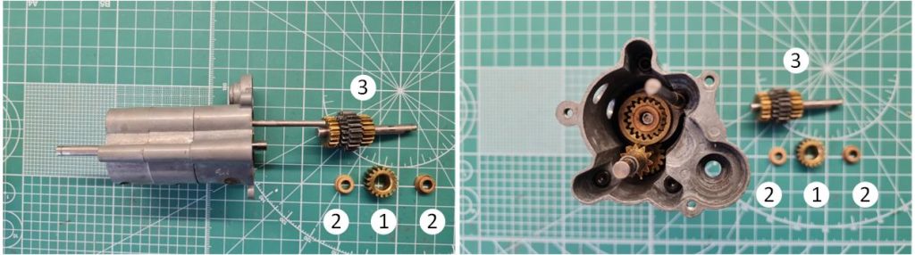
Extract the central shaft, which consists of three sets of toothed rings (identified as “3” and referred to as “main gear cluster”), from the gearbox. Separate the 18-tooth gear (marked as “1” and referred to as “idler gear”) and the two 850-sized bushings (identified as “2”) from the central shaft.
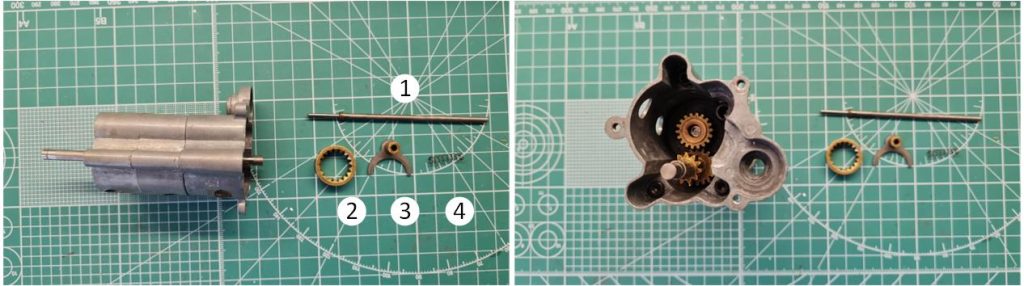
Extract the gear selection fork and shaft assembly, consisting of the shift rail (identified as “1” and referred to as “shift rail”), the selection fork (marked as “3” and referred to as “shift fork B”), the spring (identified as “4” and referred to as “shift spring A”) and the toothed ring (marked as “2” and referred to as “shift ring”).
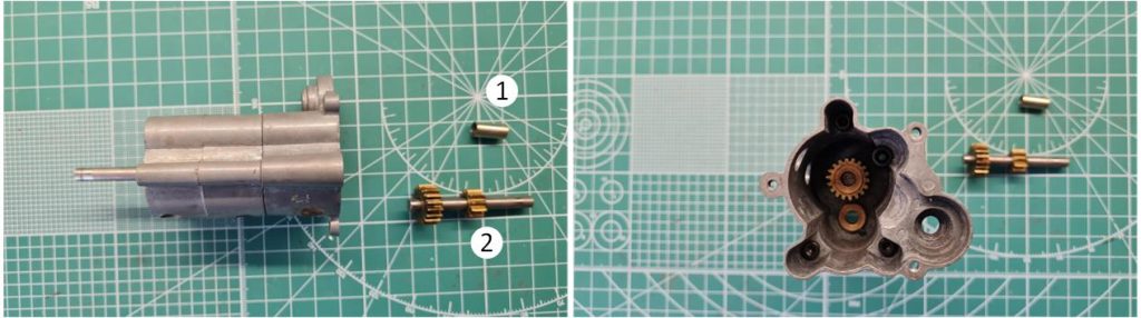
Extract the secondary shaft, which consists of two gears (identified as “2” and referred to as “Low Speed Countershaft and gear unit”) and the 5 x 12.5 mm metal cylinder (marked as “1” and referred to as “5×12.5 mm bushing”).
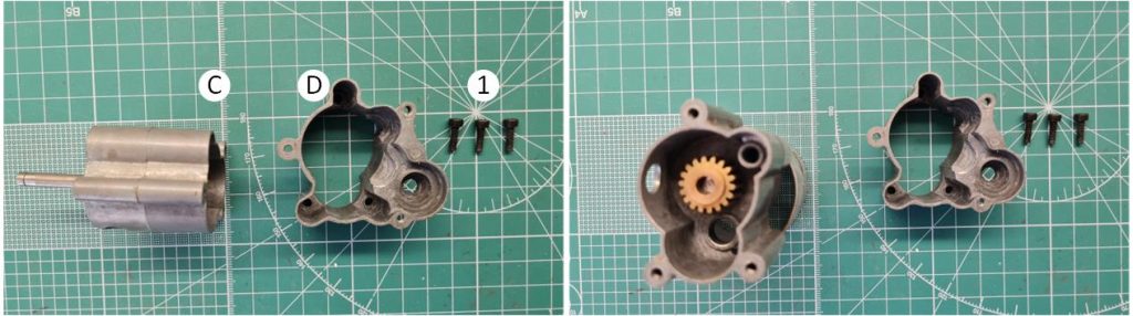
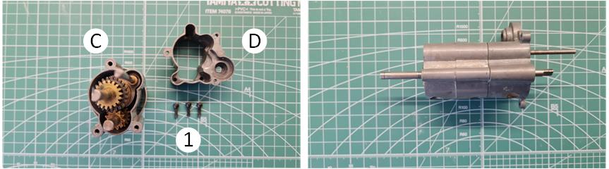
Separate section D from section C by unscrewing the three 3 x 10 mm hex socket screws (identified as “1”).
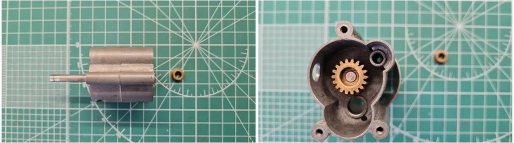
Extract the final 850-sized bushing from inside the central shaft gear.
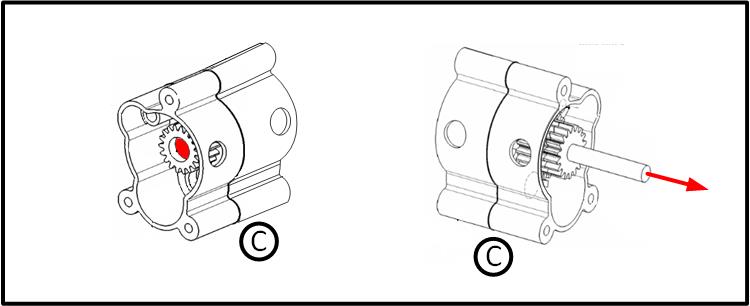
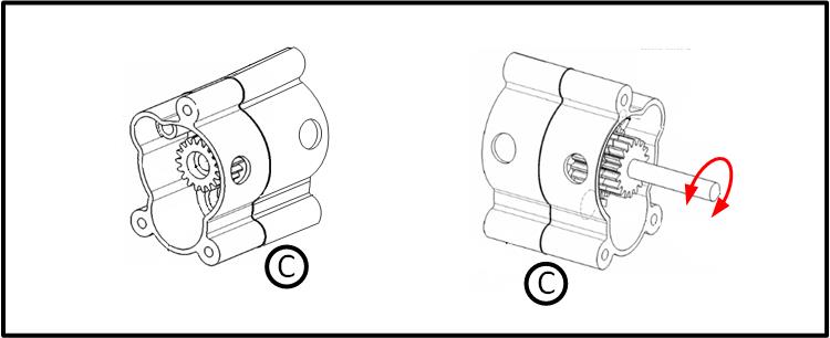
It is possible to extract the transmission shaft with the quadruple rack gear (referred to as “main gear cluster”) along with its 850- and 1150-sized bushings. This operation is not simple and requires the use of a hammer. To avoid damaging section C, it is recommended to perform this step only if absolutely necessary. To extract the transmission shaft, it must be pushed at the red-marked point on the left in the image. The transmission shaft slides out as indicated by the arrow on the right in the image above.
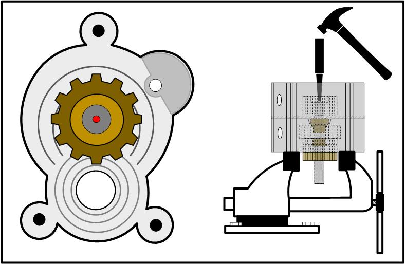
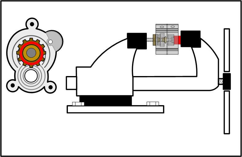
Place section C on a workbench vise to allow the transmission shaft to slide out. Position a punch at the center of the transmission shaft at the central point (highlighted in red in the image below on the left, representing the front view of section C) and gently tap the punch with a hammer until the shaft is fully removed.
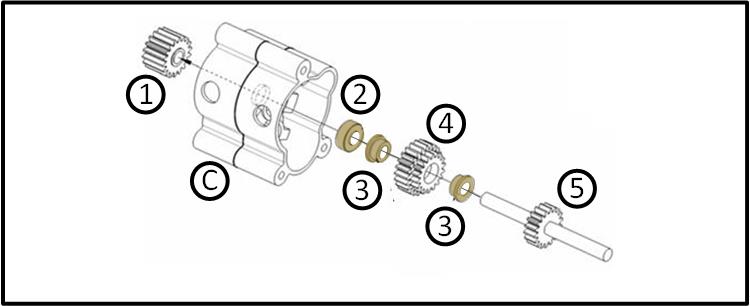
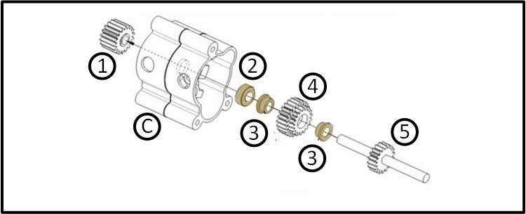
Under the action of the hammer and punch, the front gear (identified as “1”) slides off the transmission shaft (marked as “5”) along with the 1150-sized bushing (identified as “2” and highlighted in bronze), the two 850-sized bushings (marked as “3” and highlighted in bronze) and the double-rack gear (identified as “4”).
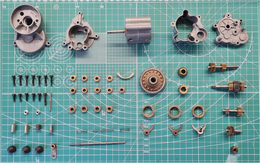
Here is an image that gathers all the parts that make up the gearbox.
Assembling a 3-speed gearbox
To assemble the gearbox housing, follow the same steps as disassembly but in reverse order, starting with the last operation and working back to the first described step. Complete section C with the through transmission shaft. In the order indicated in the image, install the 18-tooth gear with an internal hole of approximately 5 mm (identified as “1”), the 1150-sized bushing (marked as “2” and highlighted in bronze), the two 850-sized bushings (identified as “3” and highlighted in bronze), the double-rack gear (marked as “4”) and the transmission shaft with the 18-tooth gear (identified as “5”). Apply transmission lubricant to the areas indicated with the blue tube.
Position two 8 mm nuts (highlighted in red on the right in the image) as spacers and place the gearbox inside the vise as shown in the figure. By tightening the vise, gear “1” will fit onto shaft “5”. Pay attention to the orientation of gear “1” and avoid over-tightening the vise, as this may prevent the shaft from rotating. The gears should not create friction against the gearbox housing in section C.
In the image below, on the left is the front view of section C and on the right is the rear view of section C. The transmission shaft must rotate freely in both the clockwise and counterclockwise directions, as indicated in the image on the right.
Required materials:
– 1 x section C – 1 x 850-sized bushing – 1 x “Main Gear Cluster”
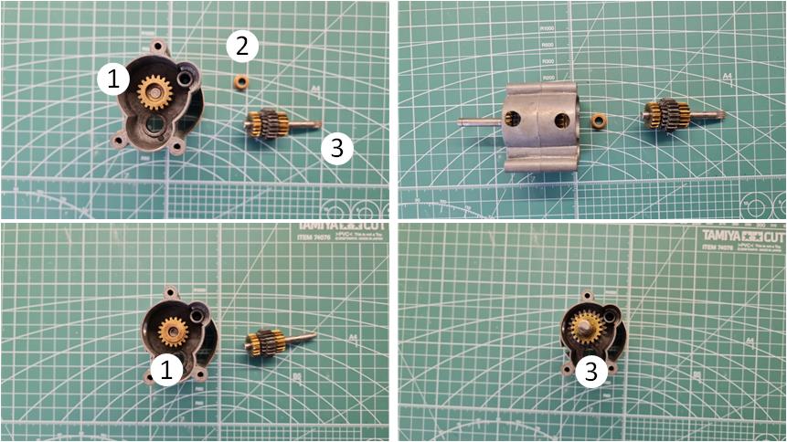
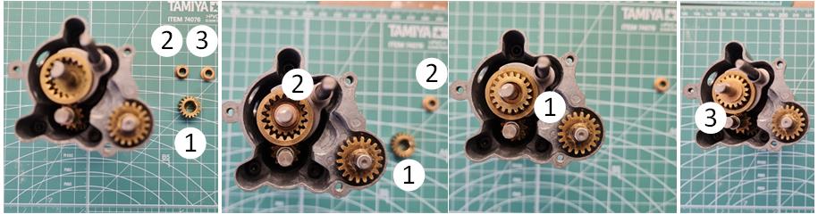
Rotate section C to work on the side where a single hollow gear is installed. The image sequence demonstrates how to:
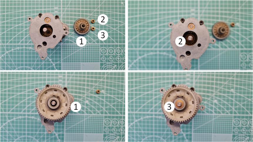
– Insert the 850-sized bushing (identified as “2”) into the hollow gear (marked as “1”). – Position the central shaft with three sets of toothed rings (identified as “3” and referred to as “main gear cluster”) into the 850-sized bushing.
Apply transmission lubricant to the areas where the shaft and bushing make contact.
Required materials:
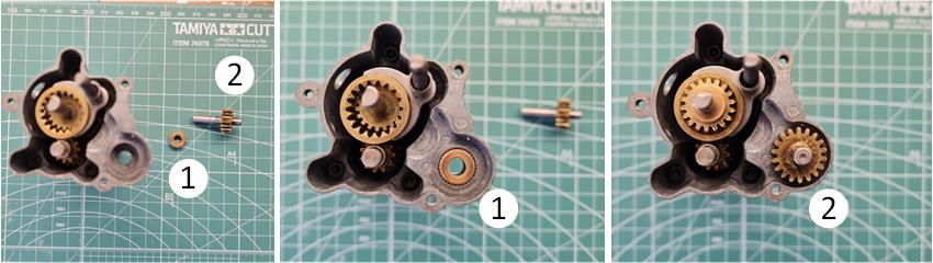
– 1 x 850-sized bushing – 1 x “Low Speed Countershaft and gear unit”
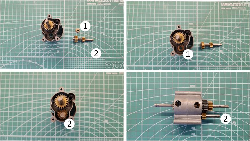
Image sequence demonstrating the process:
– Insert the 850-sized bushing (identified as “1”) into the gearbox housing in section C (image on the right in the first row). – Insert the double-gear shaft with 11 and 18 teeth (identified as “2” and referred to as “Low Speed Countershaft and gear unit”) into the bushing.
Apply transmission lubricant to the areas where the shaft and bushing make contact.
Required materials:
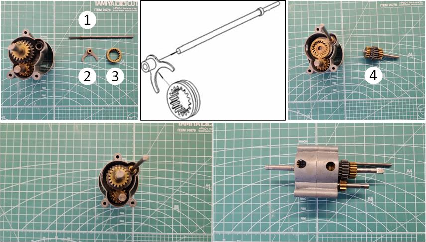
– 1 x “Shift Rail” – 1 x “Shift Ring” – 1 x “Shift Fork B”
As shown in the white background box, assemble the gear selection system consisting of the fork (identified as “2” and referred to as “shift fork B”), its toothed ring (marked as “3” and referred to as “shift ring”) and the shaft (identified as “1” and referred to as “shift rail”). The image sequence demonstrates how to install the gear selection system into the gearbox:
– Temporarily remove the central shaft with three sets of toothed rings (identified as “4” and referred to as “main gear cluster”) because the toothed ring must engage with the gears of the central transmission shaft in section C. See the image on the right in the first row. – Install the newly assembled gear selection shaft. – Reposition the central shaft with three sets of toothed rings.
Apply transmission lubricant along the gear selection shaft.
Required materials:
– 3 x hex socket screws, size 3 x 10 mm – 1 x section D
Position section D onto section C, ensuring the transmission shafts are correctly aligned. Fasten the three 3 x 10 mm hex socket screws (identified as “1”). Verify that both shafts rotate freely in both clockwise and counterclockwise directions without excessive friction.
Required materials:
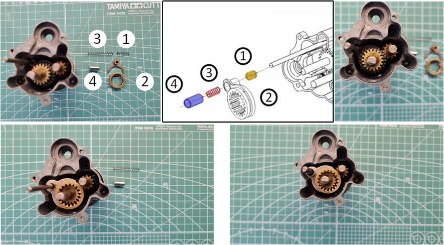
– 1 x “Shift Spring B” – 1 x “Shift Spring C” – 1 x “Bushing 5×12.5 mm” – 1 x “Shift Ring” – 1 x “Shift Fork B”
Insert the gear selection mechanism in the order shown in the white background box. The system consists of the spring (identified as “1” and highlighted in orange, referred to as “shift spring B”), the fork (marked as “2” and referred to as “shift fork B”) with its toothed ring (referred to as “shift ring”), the spring (identified as “3” and highlighted in red, referred to as “shift spring C”) and the 5 x 12.5 mm metal cylinder (marked as “4” and highlighted in blue, referred to as “5×12.5 mm bushing”). NOTE: To modify the gearbox and keep the four-wheel drive permanently engaged, refer to the section “Modifying the gearbox from 2WD – 4WD to 4WD.”
Required materials:
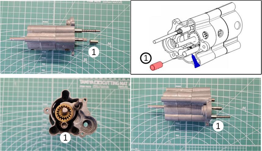
– 1 x “bushing 5×12.5 mm”
Insert the 5 x 12.5 mm metal cylinder (identified as “1” and highlighted in red, referred to as “5×12.5 mm bushing”). Apply transmission lubricant to the area indicated with the blue tube.
Required materials:
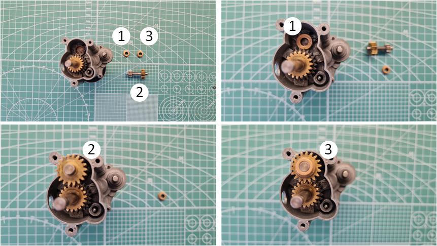
– 1 x 1150-sized bushing – 1 x “Front driver shaft and gear unit”
Insert the 1150-sized bushing (identified as “1”) into section D, followed by the transmission shaft (marked as “2” and referred to as “front driver shaft and gear unit”) with an integrated 18-tooth gear. Apply transmission lubricant to the areas where the shaft and bushing make contact.
Required materials:
– 2 x 850-sized bushings – 1 x “18T idler gear”
Image sequence demonstrating the process:
– Insert the first of the two 850-sized bushings (identified as “2”) into the central shaft. – Insert the 18-tooth gear with an internal hole of 8 mm, which fits perfectly with the 850-sized bushings (marked as “1” and referred to as “18T idler gear”). – Insert the second of the two 850-sized bushings (identified as “3”).
Apply transmission lubricant to the areas where the shaft and bushings make contact.
Required materials:
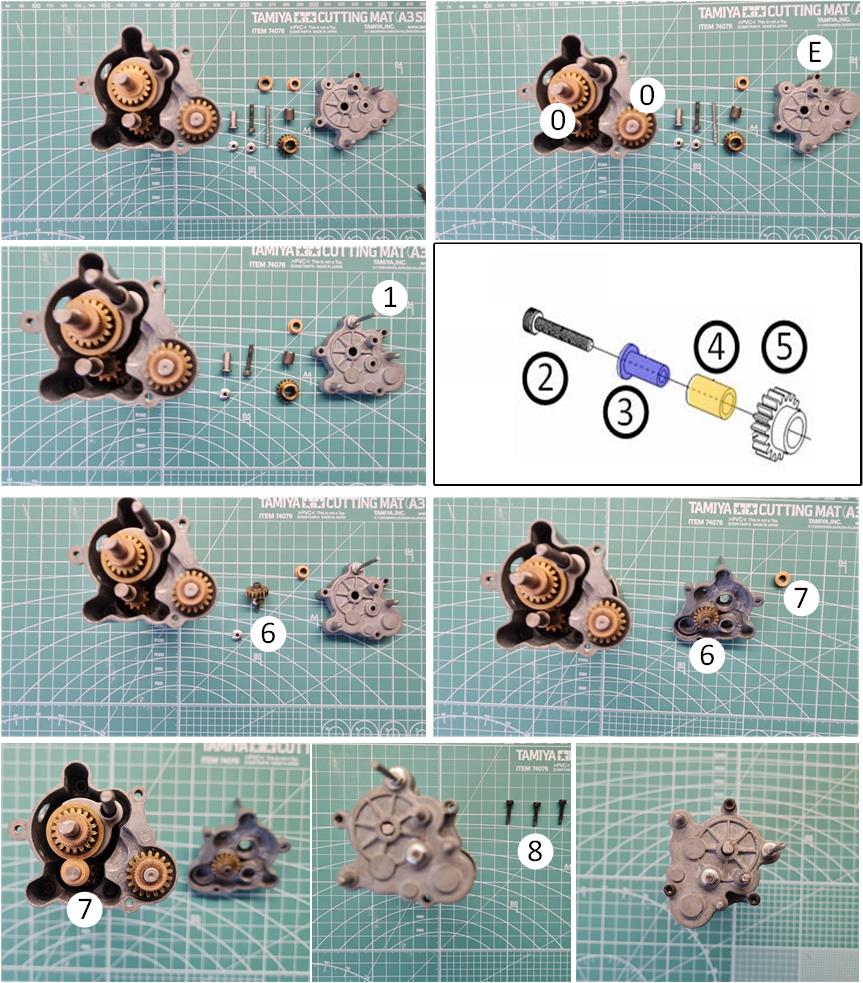
– 1 x 850-sized bushing – 2 x 1150-sized bushings – 1 x plastic bushing – 3 x hex socket screws, size 3 x 15 mm – 1 x hex socket screw, size 3 x 18 mm – 2 x flanged nuts, size 3 mm – 1 x “Front driver countershaft” – 1 x “Front driver gear” – 1 x threaded rod with one threaded end, size 3 mm – 1 x section C
Insert the two 1150-sized bushings (identified as “0”) onto the central shaft and the external lateral shaft for power transmission to the front axle. Apply transmission lubricant to the areas where the shaft and bushings make contact. Prepare section E, fastening the threaded rod (identified as “1”) and its nut—this part guides the servo motor in selecting the three gears. Rotate section E. Refer to the white background box to prepare the transmission shaft, consisting of:
– The 3 x 18 mm hex socket screw (identified as “2”). – The flanged metal bushing (marked as “3” and highlighted in blue, referred to as “front driver countershaft”). – The cylindrical plastic bushing (identified as “4” and highlighted in orange). – The 18-tooth gear (marked as “5” and referred to as “front driver countergear”).
Fasten the assembled system (identified as “6”) to section E, ensuring proper installation of the locknut on the external side of the gearbox. Insert the 850-sized bushing (marked as “7”) into the lower secondary shaft. Apply transmission lubricant to the areas where the shaft and bushings make contact. Secure section E to the gearbox within section D using three 3 x 15 mm hex socket screws (identified as “1”). When positioning section E, be careful not to improperly compress the spring.
Required materials:
– 2 x 850-sized bushings – 1 x “2nd Speed Countershaft and Gear Unit”
Rotate the assembled gearbox section to access the front side. The image sequence demonstrates the following steps:
– Insert the first 850-sized bushing (identified as “1”) into the gearbox housing. – Position the transmission shaft with double gears of 11 and 18 teeth (marked as “2” and referred to as “2nd Speed Countershaft and Gear Unit”) with the first bushing already inserted. – Insert the second 850-sized bushing (identified as “3”).
Apply transmission lubricant to the areas where the shaft and bushings make contact.
Required materials:
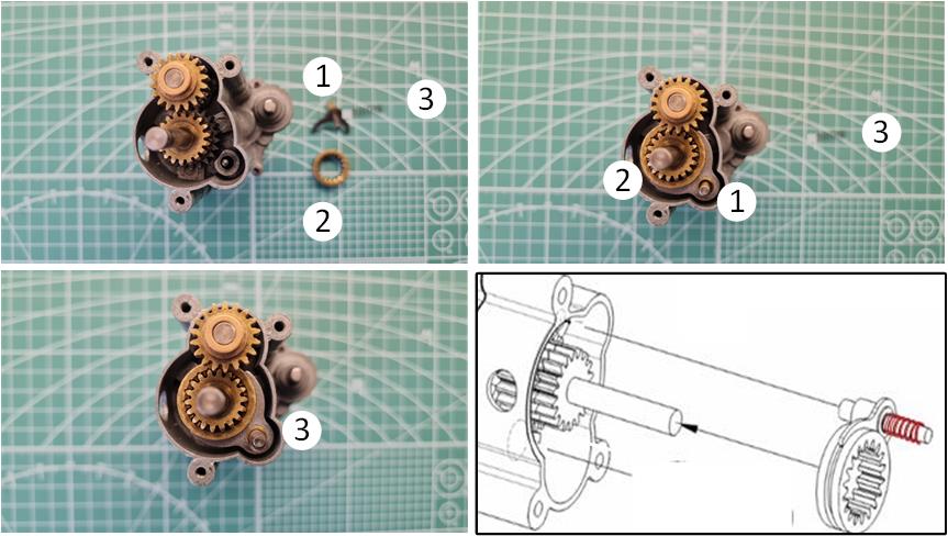
– 1 x “Shift Spring A” – 1 x “Shift Ring” – 1 x “Shift Fork A”
To complete the gear selector, assemble the fork (identified as “1” and referred to as “shift fork A”) with the toothed ring (marked as “2” and referred to as “shifting ring”). Insert the assembled system into the gearbox housing as shown in the image on the right in the second row, ensuring the spring (highlighted in red and referred to as “shift spring A”) is positioned correctly.
Required materials:
– 1 x Part B – 3 x hex socket screws, size 3 x 15 mm
Position section B onto the gearbox and fasten it using the three 3 x 15 mm hex socket screws (identified as “1”), securing section B to section C. Take extra care, as a spring is installed between sections C and B and it must not be compressed incorrectly.
Required materials:
– 1 x “Plastic idler gear” – 2 x 850-sized bushings
Image sequence demonstrating the process:
– Insert the white plastic gear (identified as “1” and referred to as “plastic idler gear”). – Insert its two 850-sized bushings (highlighted in bronze and identified as “2” and “3”).
The white plastic gear is labeled with code 4265002. Apply transmission lubricant to the areas where the shaft and bushings make contact.
Required materials:
– 1 x section A – 2 x hex socket screws, size 3 x 10 mm – 1 x hex socket screw, size 3 x 15 mm – 1 x “Dust Protector” – 1 x 1150-sized bushing
The image sequence illustrates how to position section A, which protects the only plastic gear (identified as “2”) in the gearbox:
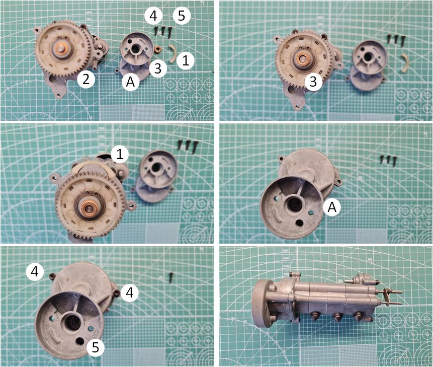
– Install the 1150-sized bushing (marked as “3”) onto the plastic gear shaft that will be housed in section A. – Apply transmission lubricant to the areas where the shaft and bushing make contact. – Insert the crescent-shaped white plastic piece (identified as “1” and referred to as “dust protector”). This component shields the lower part of the gearbox from dust and also serves as an elastic impact buffer. The crescent has one face with two small towers (one on the right side and one on the left) and another face with four small towers (two on the right and two on the left). The face with four towers should be inserted toward the rear of the gearbox so that the towers fit into the heads of the two hex socket screws. – Fasten the two 3 x 10 mm hex socket screws (highlighted as “4”). – Tighten the 3 x 15 mm hex socket screw (marked as “5”). These three screws secure section A to section B. – Position the three rubber caps. – Set the gear selection lever approximately 9–10 mm from the rear of the gearbox.
Position the motor and tighten the two 4 x 11 mm screws highlighted in red.
Ball Bearings
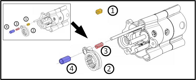
It is possible to replace the four 1150 bushings with 1150 ball bearings, as they have the same dimensions, making the process straightforward. Mechanically, the 1150 ball bearing solution performs better than an 1150 bushing. The eight flanged 850 bushings can also be replaced with 850 ball bearings, but the ball bearing and the 850 bushing have different dimensions. The flanged 850 bushing has a total thickness of approximately 4.05 mm, of which 2.50 mm is the flange thickness. The 850 ball bearing has a total thickness of just under 2.50 mm, with a flange thickness of about 0.60 mm. Comparing the two components reveals differences in flange thickness and total length. The flange thickness is particularly problematic; the flange keeps the bearing in position and separates it from the surface against which the transmission shaft or gear must not come into contact. To compensate for the 0.50 mm difference, calibration washers must be added. Calibration washers with an internal diameter of 5 mm, a maximum external diameter of 8 mm (still smaller than the bearing flange diameter) and a thickness of 0.12 mm are available on the market. By inserting four washers, it is possible to compensate for a 0.48 mm gap, which is the closest to the 0.50 mm measured. It becomes evident that replacing 850 bushings is not possible by adding only one component; five components (4 washers and 1 bearing) are required, which mechanically is not the most efficient solution. From a mechanical perspective, it is better to use 850 bronze bushings. Convert the Gearbox from 2WD – 4WD to 4WD. It is possible to modify the gearbox for constant four-wheel drive. This solution stresses all the drivetrain elements, as there is no central differential or differentials in the front and rear axles. Driving becomes significantly understeering in the second and third gears. The same understeer occurs in the first gear, but the reduced speed mitigates its effects. This causes greater stress on the transmission components. In the gearbox, engaging four-wheel drive is achieved by inserting the rear gear into the longer selection fork.
In the image below, the upper left box illustrates the steps for installing the parts to have 2WD and 4WD, while the image on the right highlights the modifications to obtain a transmission with constant four-wheel drive. To retain the ability to shift through the three speeds while always keeping the gear engaged, follow these steps:
– Remove the longer spring (identified as “3” and highlighted in red, referred to as “shift spring C”) from its position. This ensures that the fork directly contacts the metal tube 5×12.5 mm (identified as “4”). During assembly, verify that the fork (identified as “2,” referred to as “shift fork B”) engages the four-wheel drive. To achieve this, when installing section E, ensure the fork is in contact with the 5×12.5 mm tube (identified as “4” and highlighted in blue, referred to as “5×12.5 mm bushing”). – Replace the shorter spring (identified as “1” and highlighted in orange, referred to as “shift spring B”) with the longer spring (identified as “3” and highlighted in red, referred to as “shift spring C”) previously removed from its original position. This longer spring ensures the correct spacing between the two gear selection forks.
Proceed with the remaining steps, but before fully closing the gearbox, verify that the modification is effective, allowing gear shifts while maintaining constant four-wheel drive.
Problemi da affrontare dopo questa modifica:
– le quattro ruote non si inseriscono: verificare che la forcella di selezione individuata dal numero “2”(definito come “shift fork B”) sia a contatto con il tubo individuato dal numero “4” (definito come “5×12,5 mm bushing”), – le marce non si inseriscono correttamente: verificare la distanza tra le due forcelle che viene mantenuta dalla molla individuata dal numero “3” (definita come “shift Pring C”). Se la molla non va bene perché troppo “morbida” sostituirla con una molla cha sia simile a quella individuata dal numero “1” (definita come “shift spring B”) per mantenerne la rigidezza, ma lunga il doppio. E’ possibile verificare la corretta selezione di questa molla inserendo la prima marcia più ridotta: la molla non deve essere completamente compressa tra le due forcelle di selezione.
Tamiya, original figure, box art, guide book and catalogue are of TAMIYA INC, which does not endose or sponsor www.tamiyaclassic.com. Any brands, logos and trademarks represented on this website are the copyright of their respective owners.