Tamiya Wild Willy, item number 58035, was introduced in 1982 and remained on the market until 1987 in two versions: the early models featured the Short Wheel Base (SWB) version, which evolved into the Long Wheel Base (LWB) version in the second half of production. Body made of Styrene. Wild Willy chassis, the specific model in question is the LWB (Long Wheel Base) version.
Analysis of the Model to be Restored
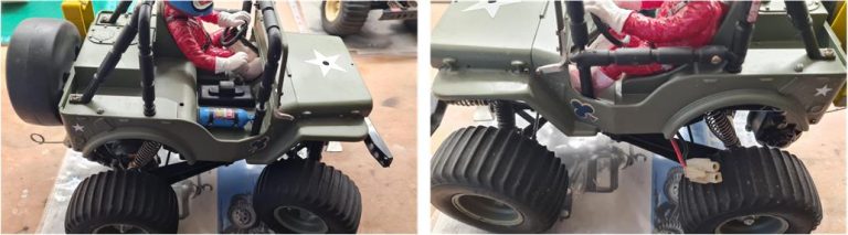
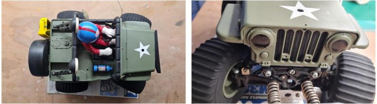
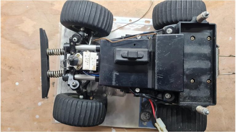
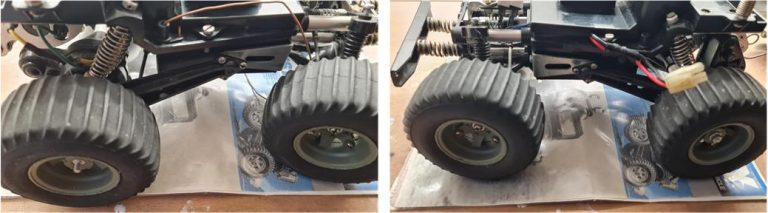
The model to be restored appears to be in good condition. A lateral analysis of the chassis, complete with the body, does not reveal any significant damage. However, on the passenger side, the bar functioning as a door is missing.
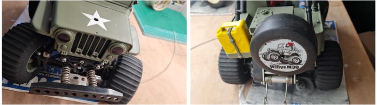
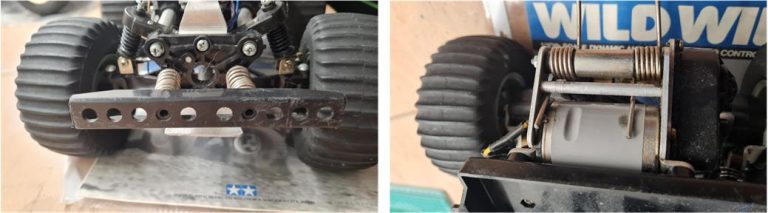
The frontal and rear analysis of the chassis, complete with the body, does not reveal any significant damage: the bumper is intact with no issues and the spare tire along with the gasoline canister is installed on the rear door of the chassis.
The analysis from above and of the radiator grille of the engine does not reveal any significant damage; however, the winch is missing.
Chassis Restoration
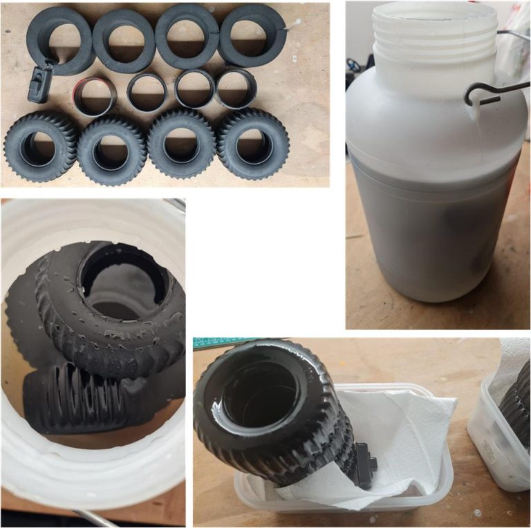
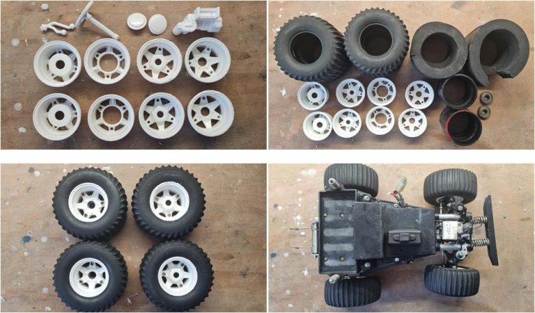
The first step involves removing the wheels and separating the rims from the tires. Inside all four tires are dense foam inserts and plastic rings. These two inserts provide rigidity to the tires, preventing them from being affected by the excessive weight of the model. Over the years, these components have preserved the tires, preventing them from becoming misshapen. While the four tires have lost some of their elasticity and show signs of aging, they have no cuts or holes and the tread is in good condition. Additionally, the rubber sheath protecting the switch is intact.
The lateral analysis of the chassis does not reveal any additional damages that were not already identified during the examination of the complete chassis with the body attached.
The analysis of the front and rear sections also does not reveal any additional damage beyond what was already observed during the examination of the complete chassis with the body attached.
To remove years of dust and grease from the tires, wash them using warm—lukewarm—water, a toothbrush with soft bristles and a bit of grease-cutting dish soap. The soap emulsifies the grease, allowing it to be washed away; without soap, the grease would simply be moved around the tire. At this point, it becomes even more apparent that the tires have aged—it’s best to treat them with glycerin to rejuvenate them. Here’s the sequence of operations for regeneration using 99% pure glycerin:
– Soak the tires in glycerin for at least a week; even a few extra days if the rubber is particularly inflexible. – After soaking, let the tires rest on kitchen paper towels for a week. During this stage, the tires will emulsify excess glycerin, so replace the paper towel at least once daily. – At the end of the treatment, the tires will regain their original appearance. For the following 5 or 6 days, wipe the tires daily with a kitchen paper towel to remove any remaining residue.
Use a container with a screw-on lid and a gasket to prevent humidity (and consequently water) from affecting the regenerative properties of the glycerin. The mouth of the container should be wide enough to accommodate even the tires of larger models without any issues. Inside, there should be approximately 5 liters of glycerin, which can be reused multiple times. Disassemble the various parts of the chassis to separate the electronics, plastic components and metal parts.
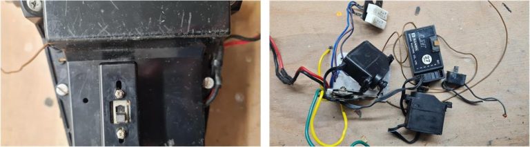
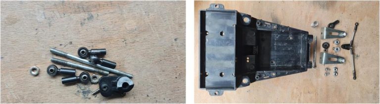
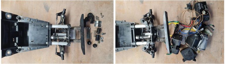
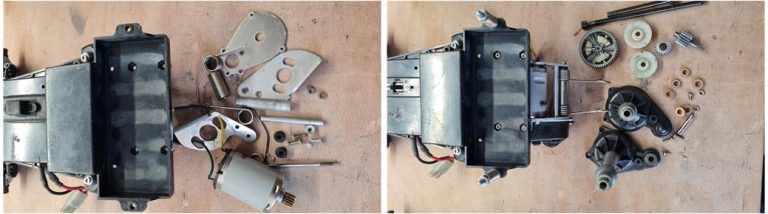
The electronics are complete and include a switch, a servo motor for steering, a servo motor for mechanical speed control and a mechanical speed control system consisting of two resistors and a metal plate (as shown in the image on the right).
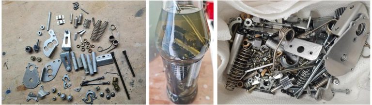
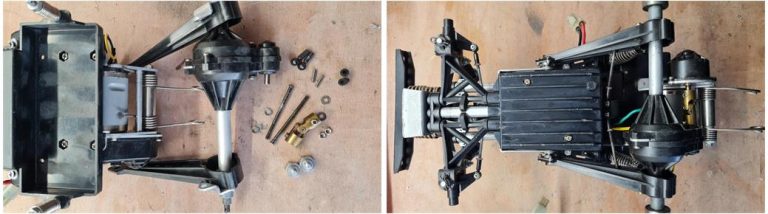
Treat the metal parts (as shown in the image on the left) by immersing them in diesel fuel for approximately one week (as shown in the center image). The diesel fuel dissolves oxidation, rust and grease. After the treatment, the pieces will change color; all oxidation, oil residues and rust will have disappeared (as seen in the image on the right). Diesel leaves an oily film that protects these parts from the action of oxygen. To ensure the smell of diesel does not linger, leave the parts exposed to natural sunlight for two or three days following the treatment. The duration of immersion in diesel and exposure to sunlight depends on the level of “stains” to be treated and how strongly the parts retain the diesel smell. Therefore, timing may vary accordingly.
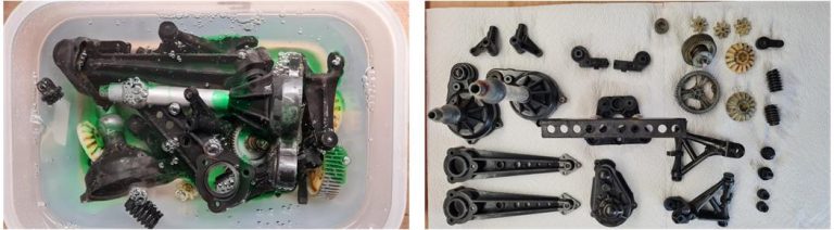
Treat plastic parts by immersing them in a solution of water and dish soap (as shown in the image on the left). The soap serves to dissolve dust and dirt and also acts as a degreaser for the various components. After two days, rinse the parts with warm water using a toothbrush to clean even the hard-to-reach areas. The clutch system of the Wild Willy chassis is the same as that of the Quattro chassis. Do not disassemble the clutch (refer to this guide for the clutch systemof this chassis). Following this treatment, place the parts on kitchen towels to dry (as shown in the image on the right).
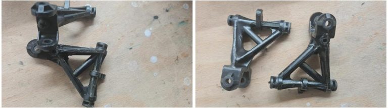
After the cleaning process, inspect the components to ensure there are no cracks, minor damage, or repairs made over time. If a part has been expertly repaired, it can be used to complete the restoration; otherwise, it should be replaced. The lower arms of the front suspension in this model are highly stressed and often break during jumps or impacts. In this case, something must have gone wrong—after cleaning, it is evident that both parts were repaired, likely using some kind of plastic glue that altered the thickness of various sections. Additionally, the previous owner inserted a screw to reinforce the structure (as shown in the image on the left). These should be replaced with new or regenerated arms to ensure proper functionality and durability during restoration.
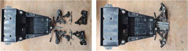
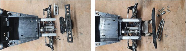
The assembly of this chassis begins with the front section, which includes the steering system, the suspension system and the front bumper. The steering arms are adjustable and equipped with ball joints, while the steering column features a servo saver system composed of a spring and several plastic components.
The lower arms of the front suspension have been replaced with new ones. The front section consists of an aluminum tubular frame, which serves as a support for the suspension system and facilitates the installation of the front bumper.
The front bumper system consists of a plastic plate on which two springs are mounted. These springs serve to absorb the impacts that the bumper endures during regular use.
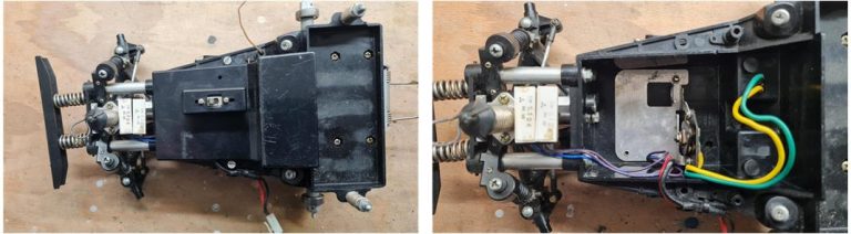
To complete the front section, only the shock absorbers are missing; the front section consists of the steering system and the suspension. The suspension shock absorbers are built with parts that are exclusive to the Wild Willy and Quattro chassis. Once the mechanical front section is complete, attention can be shifted to the electrical components, which include two servo motors, a receiver, a motor, the mechanical speed controller and a metal plate that serves as the mounting base for the electronics on the chassis.
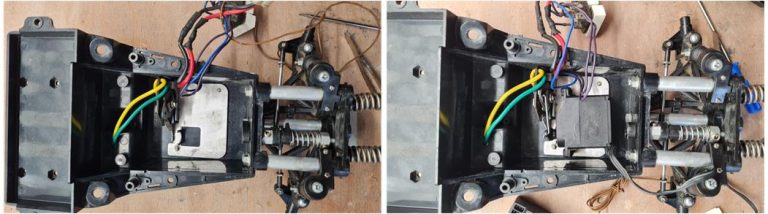
First, install the mechanical speed controller onto the aluminum plate; this assembly is then to be mounted on the lower shell. The plate is equipped with threaded holes, allowing the mechanical speed controller to be securely fastened to the plate itself and fixed inside the plastic shell. Using double-sided adhesive tape, you can then mount the two servo controls.
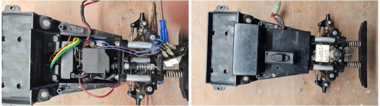
The receiver is placed in the rear compartment relative to the two servo motors. Once all the parts are properly fitted, the cables can be arranged in a way that avoids obstructing the movement of the servo motors. The upper shell of the LWB chassis differs from that of the SWB chassis; in the long-wheelbase version, there are no top openings for cables to exit from the electronics box. The battery cables exit laterally, while the electrical resistance cables for the mechanical controller exit frontally. In both cases, slots were created in both the upper and lower shells to allow the cables to pass through effectively. When all the components are in place, the upper shell can be closed by screwing in the two screws that firmly secure it to the lower shell, ensuring the cables are not pinched between the two shells during assembly.
Using a soldering iron, complete the wiring for the yellow and green cables that connect the mechanical speed controller to the motor. Next, assemble the rear cage, which houses the motor and the two springs designed to stabilize the model when running on its rear wheels. The motor includes a heat-shrink plastic cover, a characteristic feature of the Wild Willy model. The construction of the differential is straightforward and features a Teflon gear, which replaces the metal equivalent found in the short-wheelbase (SWB) model. This improvement is also present in the Quattro chassis.
The rear system consists of the rear suspension bridge; there are some minor differences compared to the previous model, but mechanically, the suspension movement remains unchanged.
Among the inserts of the four tires, there is a foam piece that is slightly damaged. When placed inside the tire, it takes its correct shape and the plastic ring helps maintain its form—it’s best not to use glue to secure it. The rims have been treated with 99% pure alcohol, followed by two coats of fine primer Tamiya 87044 and two coats of matte white Tamiya TS27. The wheels have completed their glycerin treatment. Now they are ready to be assembled with the tires, foam inserts, and hard plastic inserts.
Body Restoration
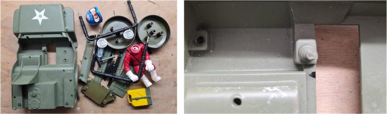
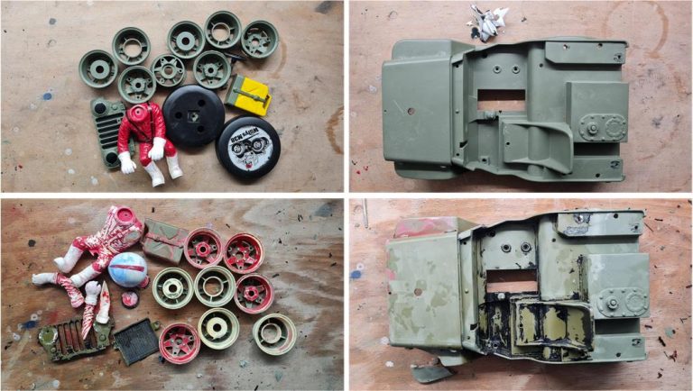
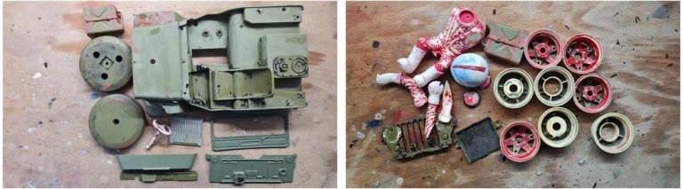
The first step involves disassembling the body into all its components (as shown in the image on the left) and inspecting for any hidden damages. Upon examination, it becomes immediately apparent that the gear shift lever is missing (as shown in the image on the right), having broken off at its base.
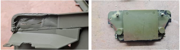
There are two components that require attention: the left front bumper (as shown in the image on the left), which appears to have undergone a repair and the radiator at the front, which is deformed, likely due to a frontal impact (as shown in the image on the right).
Treat the body and its components (rear tire, gasoline canister, driver figurine, etc.) using 90% pure alcohol (commercially, you can find alcohol as pure as 99%; opt for a version without added colorants or fragrances). Start by removing all stickers. Alcohol reacts with paint and glue, allowing previous layers of paint to be stripped and hidden damage to be revealed. The sequential steps for treatment are as follows:
– Immerse the parts in alcohol for 48 hours. – Remove the parts from the alcohol. – Use kitchen paper towels or a toothbrush with stiff bristles to mechanically remove the layer of paint.
Underneath the initial green paint layer, there is a black layer. In some cases, the green paint was applied over stickers that had not been removed.
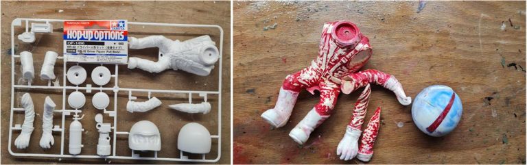
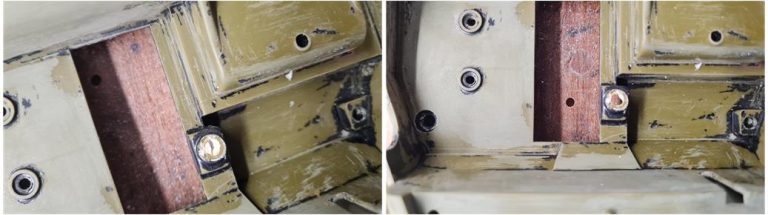
Repeat multiple cycles to ensure all layers of paint are removed. Components that were repaired using glue will detach during the process, as the alcohol chemically reacts with the adhesive, weakening its grip. At the end of the treatment, the evaluation reveals that repairs are required for the left front fender, the rear left corner and the rear shell of the spare tire.
For the driver figurine and the front winch (which are missing from the set), a new parts set is available, code 54496, designed for the Wild Willy II, which is identical to the one used in the Wild Willy I. The driver figurine has no missing or broken parts, but some components became detached when the alcohol dissolved the glue that was previously used to attach the arms.
The gear shift lever is broken, with only a very small part remaining, which is glued to the body. Here’s the sequence of steps to repair it, as illustrated in the images:
– A new gear shift lever is available from the 54496 set. Begin by removing the remaining piece of the old gear shift lever using cutting pliers. – Use a hand drill to create a small hole at the base of the gear shift lever. – Enlarge the hole by working on it with a cylindrical metal file.
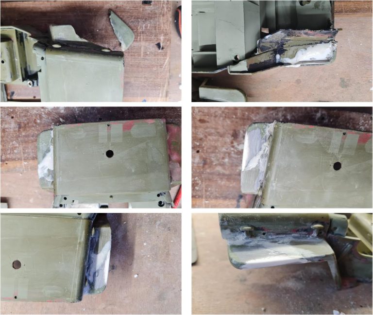
To repair the front section of the body where the left fender is broken, follow these detailed steps:
– Using a brush, apply a dense solution of acetone and styrene along the fracture line—both on the chassis and the detached fender piece. This solution bonds the two components and stays precisely where it’s applied. – Use a wooden clothespin to firmly hold the fender against the body while the solution sets. – Cut a strip of styrene measuring 0.5 mm in thickness and 3 mm in width. This piece acts as a reinforcement, much like a patch over the broken area. Apply the dense acetone-styrene solution to the lower part of the bumper using a brush and position the styrene strip. The solution adheres without dripping. – Brush a fluid acetone-styrene solution along the upper part of the joint to ensure penetration between the two parts, creating a seamless bond. – After 24 hours, use 1,000 and 1,200 grit sandpaper to smooth out the surface, removing any excess solution and achieving a clean finish.
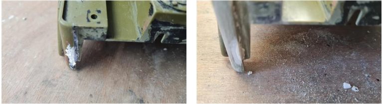
The rear left corner has a missing section. To address this:
– Apply a dense solution of acetone and styrene to the affected area to rebuild the missing portion. – Allow it to cure for 24 hours. – Once set, use the other side as a reference to restore the original shape. Carefully work on the surface with abrasive paper and a metal file to refine and match the contours.
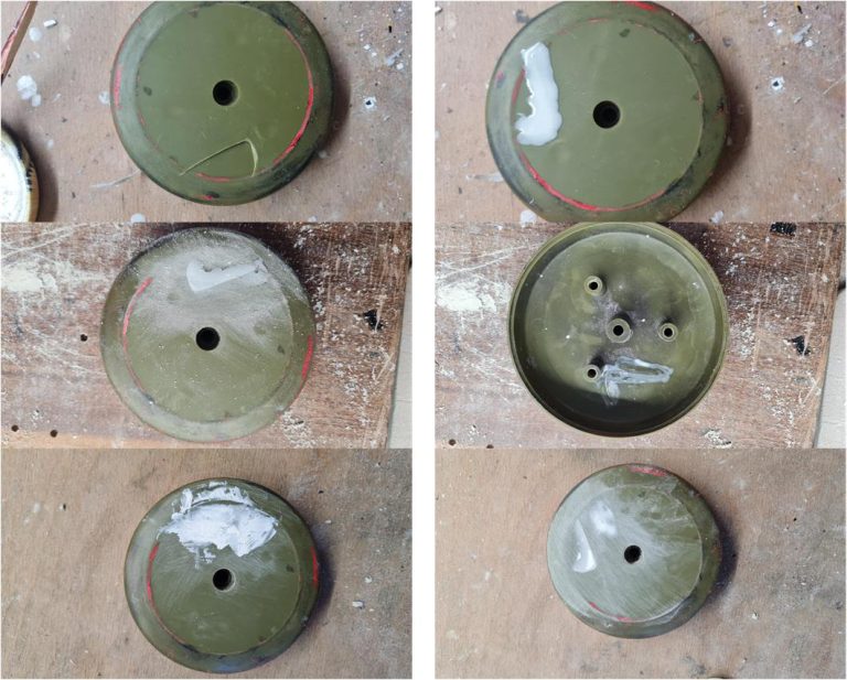
To repair the rear shell of the spare tire damaged from impact, follow this detailed procedure:
– Using a brush, apply a liquid solution of acetone and styrene along the crack. – Carefully widen the crack by flexing the plastic to allow the solution to penetrate thoroughly into the break. – Let the solution cure for 24 hours to bond the parts effectively. – Use 1,200 and 1,500 grit sandpaper to work on the external surfaces, removing any imperfections. – Apply a thin layer of filler on the external surface for a smoother finish. – After 24 hours, sand the external surface again with 1,200 and 1,500 grit sandpaper to refine it further. If the acetone and styrene solution was applied correctly, minimal traces of filler should remain after this final step.
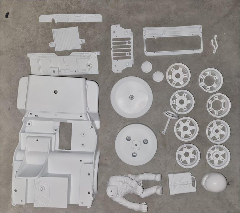
These are the parts after three coats of fine white primer Tamiya code 87044 have been applied.
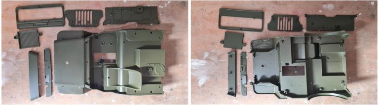
Top and bottom view of the parts that have been coated with multiple layers of olive green Tamiya TS5. The coats have been applied to all internal and external surfaces.
Prepare the following glossy effect colors: – X2 White for the pilot’s helmet. – X3 Royal Blue for the stripe on the driver’s helmet. – X6 Orange for the two turn indicators on the front grille. – X7 Red for the fire extinguisher installed on the roll bar on the driver’s side, the upper shell of the driver’s helmet and the left and right reflectors on the rear body. – X8 Lemon Yellow for the fuel can installed on the rear hatch. – X10 Gun Metal for the radiator behind the front grille. – X11 Chrome Silver for the two front headlights. – X18 Semi-Gloss Black for the winch, steering wheel, windshield seal, wiper, circular trim around the two front headlights, driver’s seat belts, visor opening outline on the driver’s helmet, gear shift and reduction knobs and left and right rear wheel covers.
Prepare the following matte effect colors: – XF2 Flat White for the pilot’s suit, or alternatively, TS27 Matt White. – XF7 Flat Red for the driver’s gloves. – XF8 Flat Blue for the upper part of the seat belts. – XF10 Flat Brown for the driver’s boots. – XF16 Flat Aluminium for the diesel tank cap, extinguisher nozzle, NOS cylinder nozzle and straps for the NOS cylinder and extinguisher. – XF23 Light Blue for the nitrous oxide (NOS) cylinder. – XF56 Metallic Grey for the hook, steering hub, winch cable and shift and reduction levers. – XF57 Buff for the spare wheel cover, or alternatively, TS46 Light Sand.
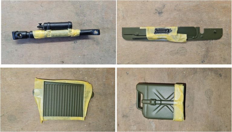
Once all colors are prepared, mask the parts to be painted and begin applying the various coats of paint. Press the masking tape firmly with your fingers to ensure it adheres well to the surface. Avoid leaving gaps between the tape and the surface, as paint may seep through, creating unwanted streaks of color.
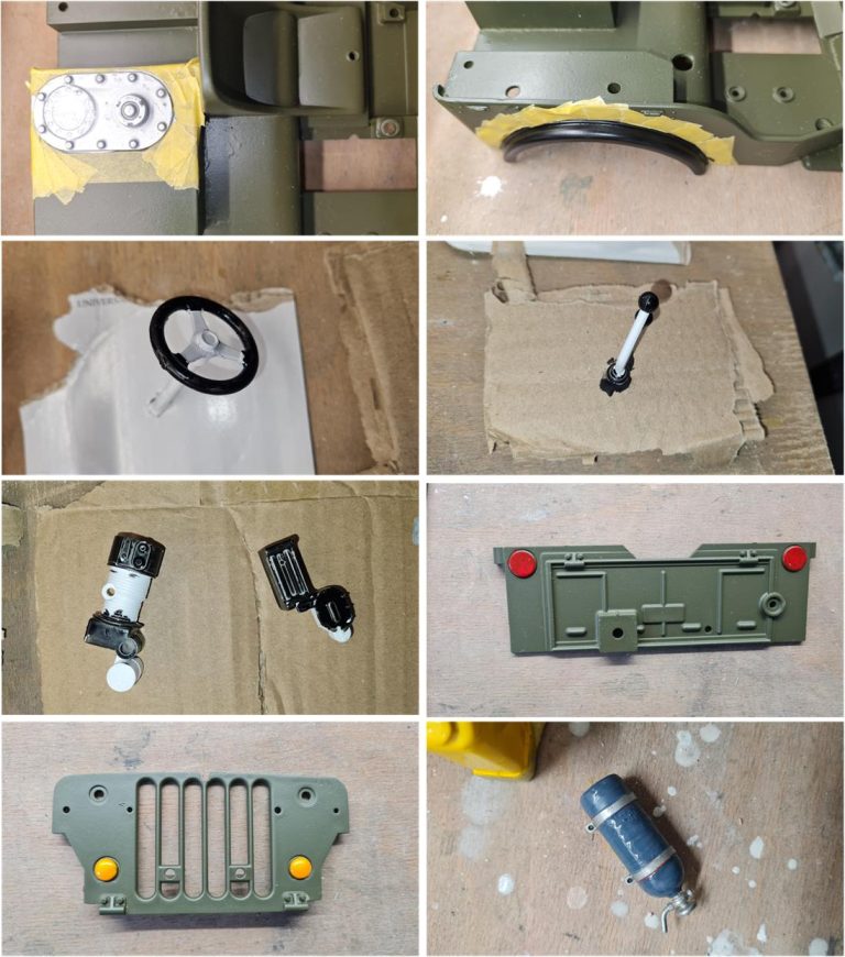
General Rule: Apply multiple coats of each color until the final color completely covers the surface. Use alternating brush strokes, ensuring that each coat is applied in a direction perpendicular to the previous one. Go over the painted surface several times to evenly distribute the paint and allow at least 12 hours between each coat. Apply paint to masked areas as well as to parts too small to be masked, such as turn signals, brake lights, reflectors and the windshield seal. This step requires a steady hand and a small-sized brush. Apply paint sparingly to avoid overdoing it—it’s better to go over the area multiple times than to stain the body.
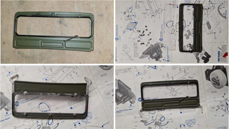
Apply Semi-Gloss Black to the edge of the glass, corresponding to the rubber seal and to the windshield wiper. The glass is a shaped piece of plexiglass; in this case, a new original piece is available. Screw in the four nuts and bolts securing the glass to the windshield, then the four nuts and bolts that fasten the two supports serving as hinges. Once installed, the plexiglass is so transparent that it is almost invisible.
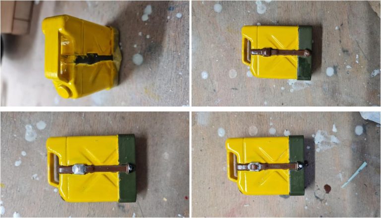
Sequence of images showing how to apply various colors to the fuel can:
– Mask the can; press with your fingers to ensure the tape adheres well to the surface, preventing yellow streaks from seeping between the tape and the surface. – Apply flat yellow X8 to the can; the yellow must completely cover the olive green. – Remove the masking; if there are no yellow streaks on the olive green, proceed. Otherwise, spray olive green TS5 onto a piece of cardboard to use as a painter’s palette; use a brush to apply the green and cover the yellow. – Apply matte brown XF10 to the strap (flat brown X9 can also be used). – Apply matte-effect black X18 to the cap and the buckle of the strap (the small triangle located at the bottom of the can). – Apply gray X11 to the buckle of the strap and the screw that secures the strap. – If too much gray is applied to the buckle, it will cover the brown rectangle of the strap. After 12 hours, reapply matte brown XF10 to the rectangle.
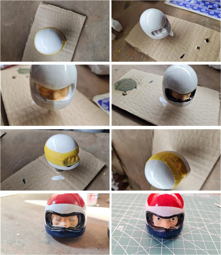
Sequence of images showing how to apply colors to the pilot’s helmet:
– Apply flat white X2 to the pilot’s helmet (alternatively, TS 26 can be used). – Apply pink to the face (there are many options available on the market; choose the preferred one). – Apply matte-effect black X18 inside the visor, taking care not to cover the pink. – Mask the helmet, leaving the red and blue stripe exposed; as in previous cases, press with your fingers to ensure the tape adheres perfectly to the helmet and prevents the paint from seeping through. – Apply flat red X7 and flat blue X3. Be careful: for the shell, it is better to start applying the color from the center and move outward towards the masking, as this reduces the likelihood of paint seeping between the surface and the tape. – Apply the face color—many skin-tone paints are available on the market; select the one that best suits your taste, – Using the toothpick-tip technique, apply matte white XF2 for the eyes and matte black X18 for the pupils.
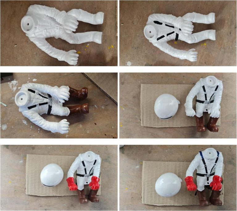
Sequence of images showing how to apply colors to the pilot figure:
– Apply matte white XF2 to the body; TS27 can also be used. – Apply matte-effect black X18 to the seat belts. – Apply flat gray X11 to the seat belt buckles. – Apply matte brown to the boots. – Apply matte red XF7 to the gloves. – Apply matte blue XF3 to the rubber reinforcements on the upper part of the seat belts.
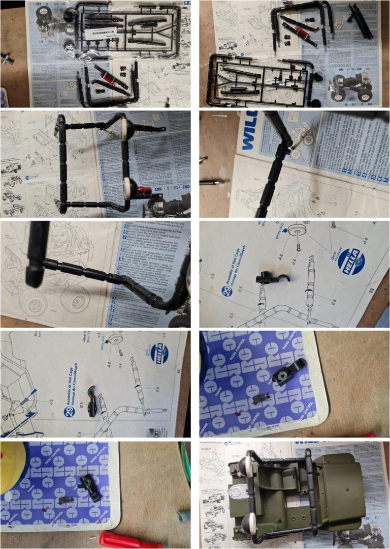
Prepare and install the roll bar, noting a complication: the passenger bar’s C-pin is missing. This part can be found in set 10115255 for the Wild Willy II. The pin is almost identical to the original but differs in the tower section, where the screw position is higher (see the C-pin for Wild Willy II in the image on the right in the second row and the C-pin for Wild Willy in the image on the left in the third row). Sand down the Wild Willy II pin with sandpaper until the tower is completely removed, apply a coat of matte black paint, wait 12 hours and then assemble the parts.
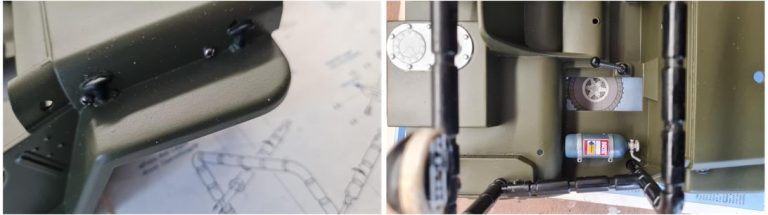
Assemble the NOS cylinder to the chassis, securing it with the four screws for the front inner fenders, along with the gear shift and reduction levers.
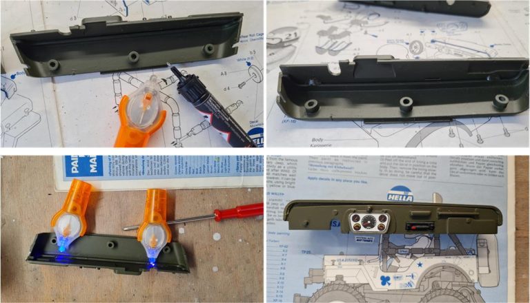
Glue the instrument panel – radio – glove compartment to the dashboard using an adhesive that hardens when exposed to UV rays. Apply two drops at the ends of the parts to be glued, without overdoing it. Once hardened, this adhesive remains very elastic and if necessary, the parts can be separated by scoring the surface with a utility knife.
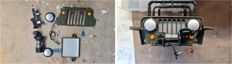
The front winch consists of several parts and a piece of black wire is required to simulate the hook cable. The radiator and grille must be glued together; as with the dashboard, UV-curing adhesive was used. This adhesive offers several advantages: once cured, it remains flexible, solidifies only when exposed to UV light—allowing time to correctly position the components before bonding—and requires application only at specific points to secure the parts. After installing the winch onto the grille, the grille must then be mounted onto the chassis.
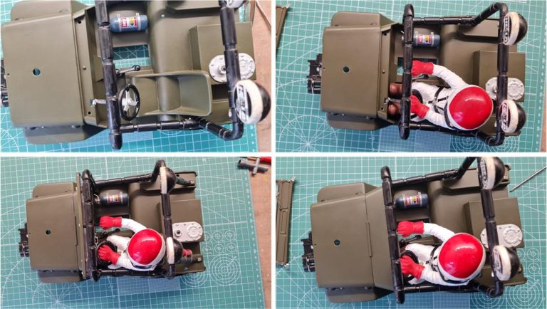
Complete the cockpit by installing the pilot figure with the steering wheel. The steering wheel is equipped with a column that fits into the main body of the chassis. The pilot figure and steering wheel must be inserted together into the cockpit; space is limited, so they need to be positioned simultaneously. First, position the steering wheel by inserting the beginning of the column into the frame, then place the pilot figure. At this point, push both the steering wheel and pilot figure into their final position. The steering column is meant to be glued to the frame, but the installation is so precise that it remains securely in place, making the application of glue unnecessary. To facilitate installation, it is advisable to use a long screw to secure the pilot figure to the seat. If the pilot figure does not fit perfectly between the steering wheel, pedals and gear lever, the long screw ensures it stays attached to the chassis. After installing the pilot figure and steering wheel, position the dashboard and fasten it with two screws. The windshield requires two screws to function as hinges and a third screw secures it to the roll bar.
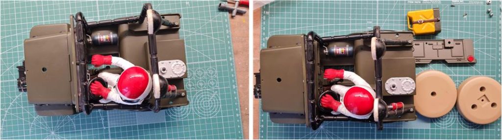
To complete the chassis, only the tailgate with the spare wheel and the reserve fuel canister is missing. All parts have been painted and it is necessary to assemble them onto the chassis. The order to follow is precise:
– Install the fuel canister on the tailgate and insert the nut into the designated compartment, which will be used for the spare wheel bolt. – Attach the assembled unit to the chassis using three nuts and bolts (one central and two lateral). – Assemble the spare wheel with three self-tapping screws. – Install the spare wheel onto the chassis with the central screw.
Now it is possible to join the body to the frame; only the stickers are missing.
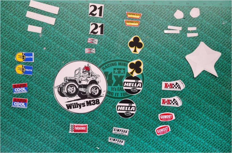
The final step is to prepare the stickers and apply them.
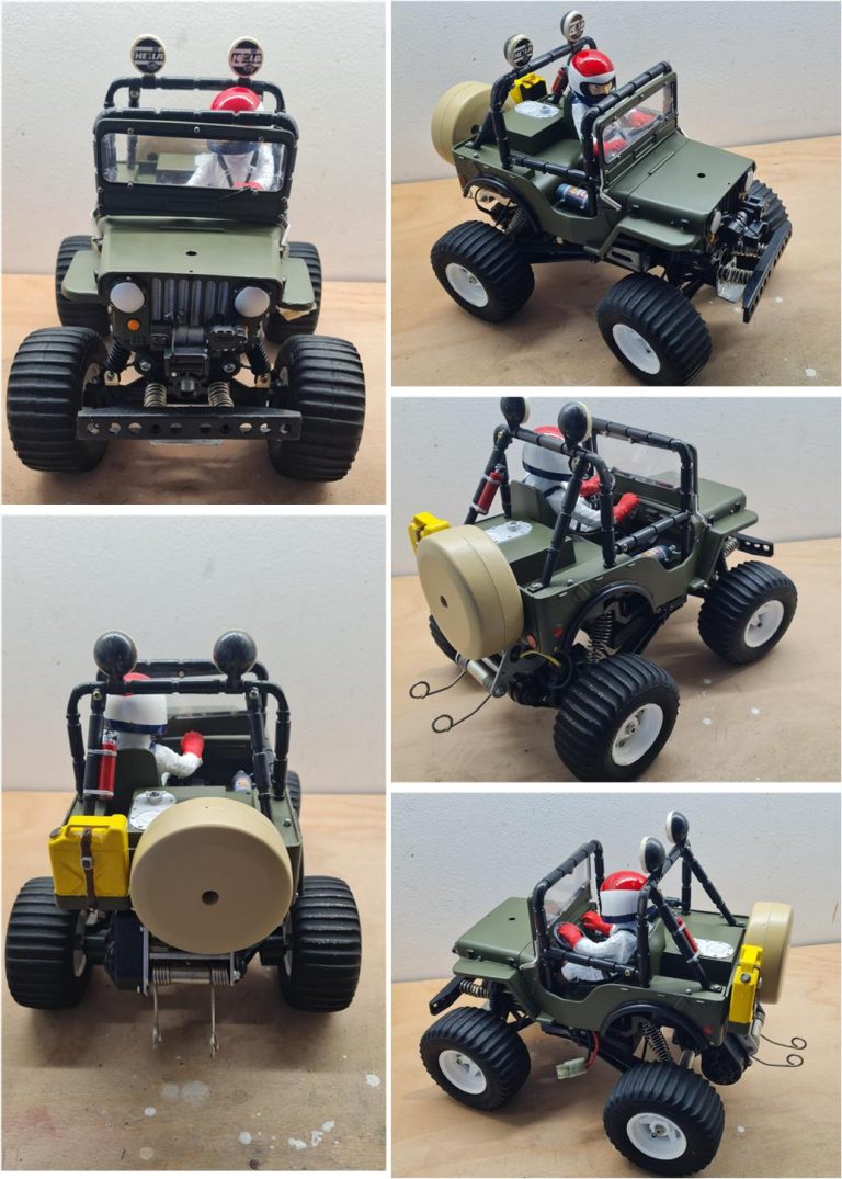
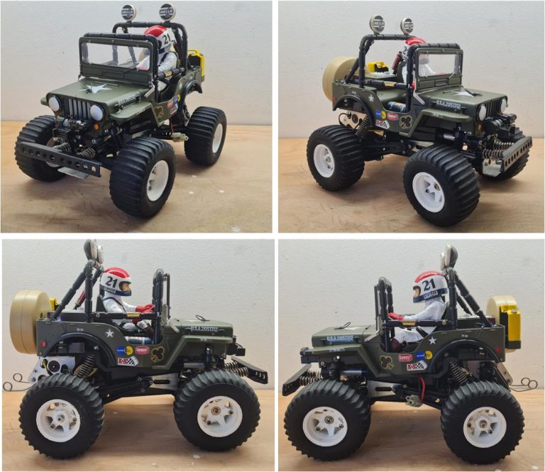
Restored model
Images showing the finished model.
Tamiya, original figure, box art, guide book and catalogue are of TAMIYA INC, which does not endose or sponsor www.tamiyaclassic.com. Any brands, logos and trademarks represented on this website are the copyright of their respective owners.