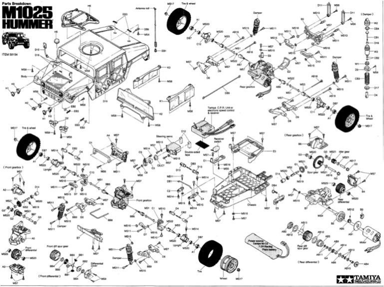
Model Tamiya Hummer, model number 58154, released in 1995 and available on the market until 1999 Styrene body TA‑01 chassis, long‑wheelbase 280 mm version
Project
The Hummer features the TA01‑series central plastic tub chassis, with the wheelbase extended from the standard 260 mm to 280 mm. As of 2026, this modification is available for the Hummer and the JGSDF Light Armored Vehicle. To lengthen the wheelbase, Tamiya replaced both the front and rear suspension arms. The front and rear suspension arms are built by joining two parts together. To better distinguish these long‑wheelbase models from the standard‑wheelbase ones, Tamiya changed the color of the front and rear gearbox housings from red to black.
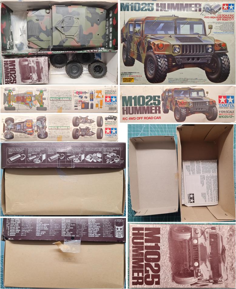
The purchase also includes the box, which is in good condition. Inside the box, the small‑parts storage tray is also included. In this case, the blister for the motor, suspension and mechanical speed controller is separate; therefore, this box is in good condition.
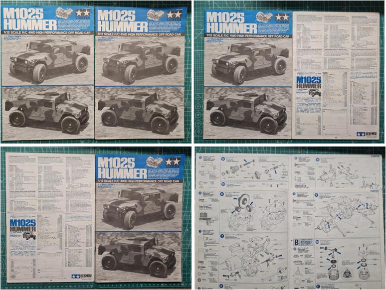
The purchase lot includes two identical instruction manuals, both in excellent condition. One of the two will be placed back inside the box at the end of the restoration so it can accompany the chassis, while the other will be stored on the workshop shelves until a suitable place is found for it.
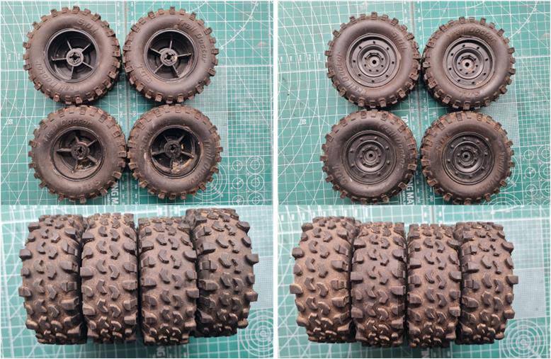
The wheels consist of the tires, part number 19445529 (set of four pieces), to which the rims, part number 19335205 (also a set of four pieces), must be added. The ones included in the lot are in perfect condition and only show some mud stuck to the tread. The tires have no cuts and are not worn. The rims show no cracks or signs of impact from rolling against obstacles. These parts are not particularly rare within Tamiya’s lineup; for example, they are shared with the JGSDF Light Armored Vehicle, model number 58326 and the Mercedes‑Benz Unimog, model number 58457.
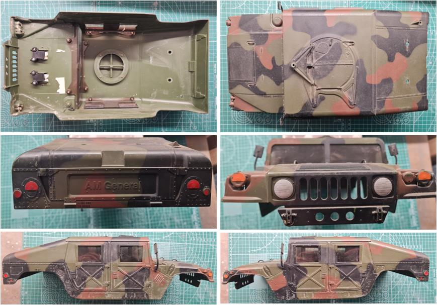
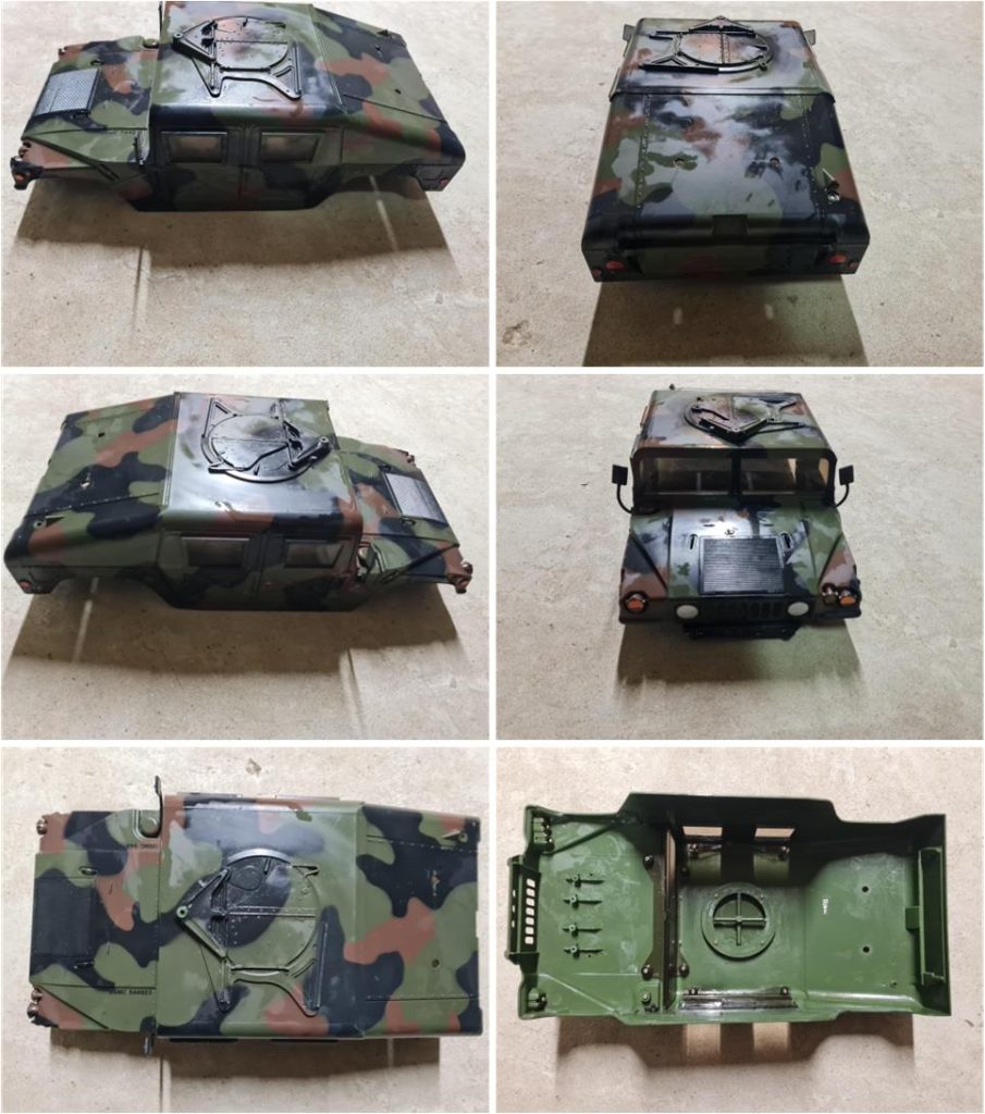
The body is made of styrene, with cockpit windows in plexiglass; the windows are divided into three pieces: windshield, left side window and right side window. It includes all additional parts such as the two rear‑view mirrors (image on the right of the second row), the two handles on the hood, the hatch of the central turret and the three front lights. There are no missing parts or impact‑related breaks. The paintwork was done properly following the manual’s instructions and the camouflage pattern is very well executed.
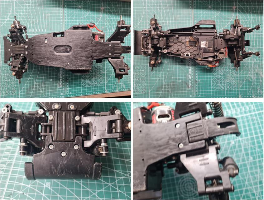
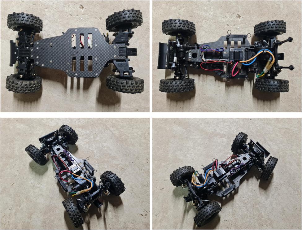
The chassis has all plastic parts in the correct color: black. From the images, the condition of the underside is clearly that of a used model (image on the left of the first row). The tub has certainly seen better days, but the front bumper (image on the left of the second row) and the rear impact guard (image on the right of the second row) are present. The suspension arms are the original ones (images in the second row) and are in better condition than the central section. The two rear body posts used to support the body shell are present (image on the right of the first row), as well as the front latch used to secure the body (stored separately in a small bag inside the box).
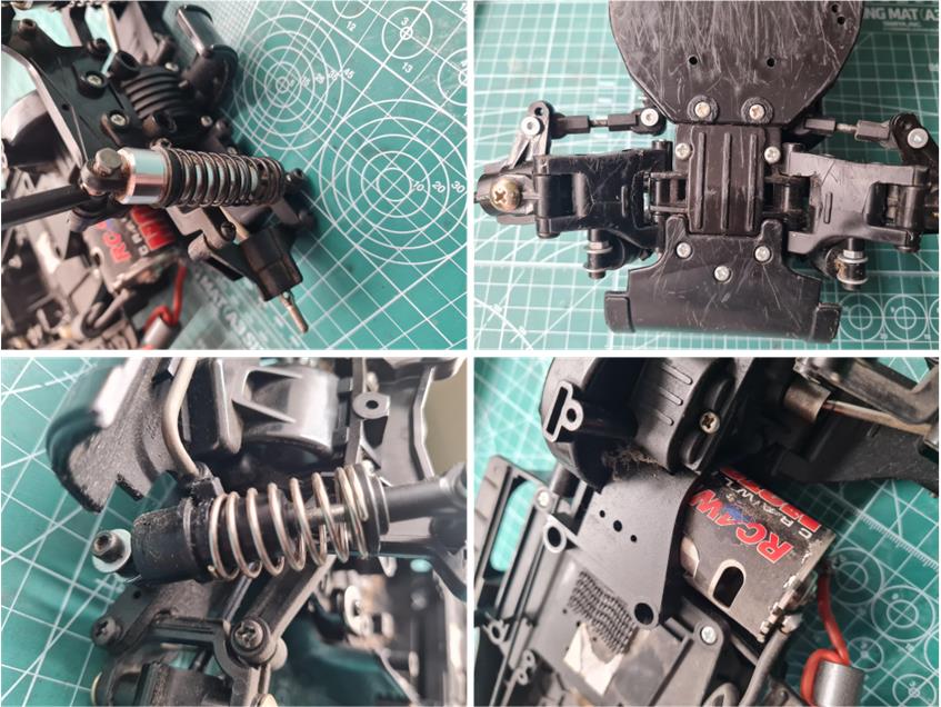
There are some non‑original parts that are clearly customizations made by the previous owner. The rear shock absorbers (image on the left of the first row) are long‑travel units made of light alloy (product by Ansmann Racing, part number 201000039, described as “aluminium damper 95 mm”). The goal was almost certainly to increase suspension travel to improve handling during jumps. The steering tie rods (image on the right of the first row) are reinforced and feature an integrated ball joint. The likely intention was to prevent these parts from breaking on rough terrain. The front shock absorbers are mounted upside down and are not the factory‑specified version. The electric motor (image on the right of the second row) is a high‑performance unit that was not included in the original kit.
This restoration aims to return the model to the condition it would have had in 1995, while adding a number of accessories to improve performance:
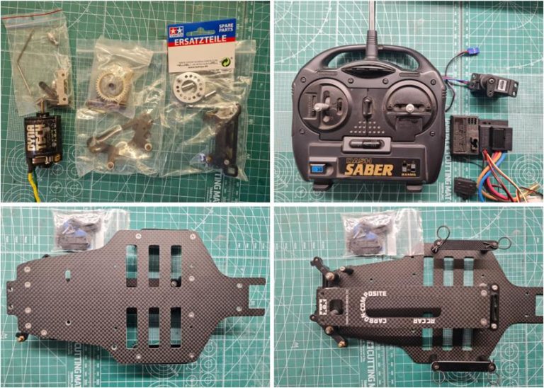
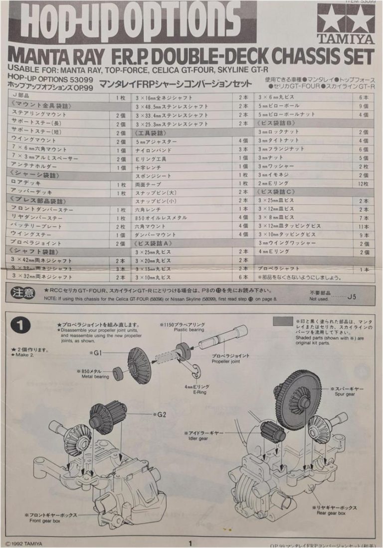
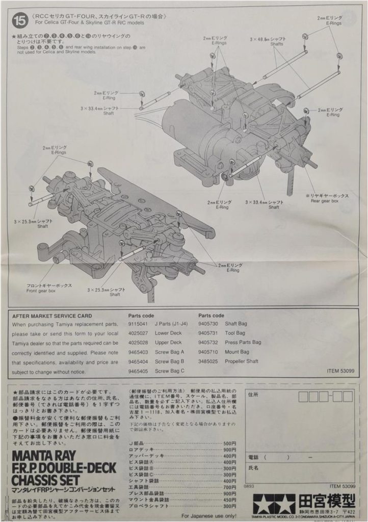
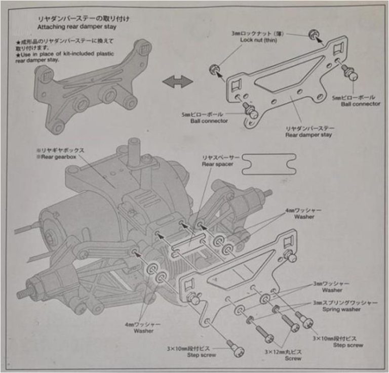
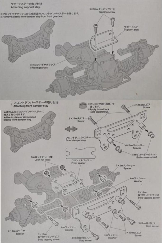
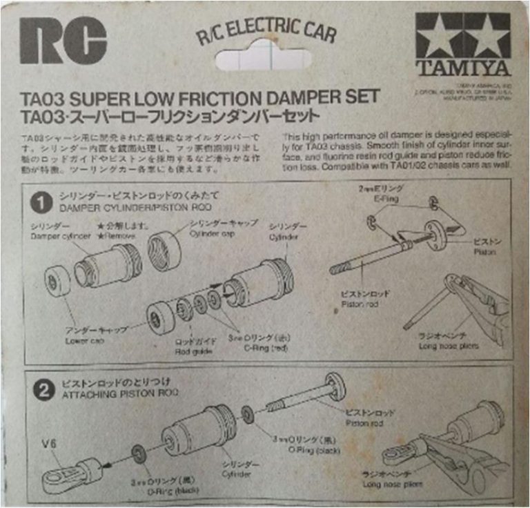
– full F.R.P. chassis, part number 53099, described as “Manta Ray FRP Double‑Deck Chassis Set (DF01/TA01)” – F.R.P. front damper stay, part number 53193, described as “FRP Front Damper Stay TA01 02” – F.R.P. rear damper stay, part number 53194, described as “FRP Rear Damper Stay TA01 02” – Dynatech motor, part number 53001 – aluminum motor mount, part number 53142, described as “4WD Rally & Touring Car Aluminium Motor Mount” – low‑friction alloy dampers, part number 53280, described as “Super Low Friction Alu Damper Set” – TEU‑101BK electronic speed controller complete with Sanwa transmitter
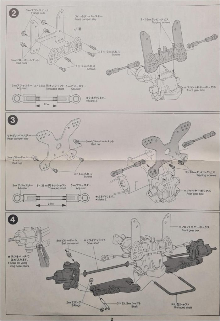
It is necessary to verify whether the rear anti‑roll bar can be installed, since it was originally designed for the TA02 chassis; however, the different suspension arms used on the long‑wheelbase TA01 may make its installation possible. The relevant set is number 53189, described as “4WD Touring and Rally Car Rear Stabilizer Set for TA02 Chassis”. Construction manual for the carbon‑fiber chassis, set number 53099.:
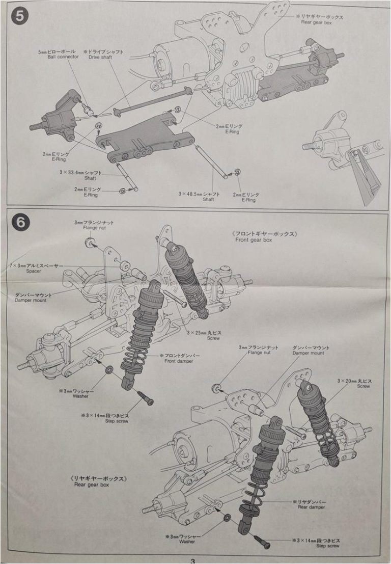
Construction manual for the two carbon towers, part numbers 53193 and 53194. In this case as well, compatibility between the body shell and these fiber plates must be verified.
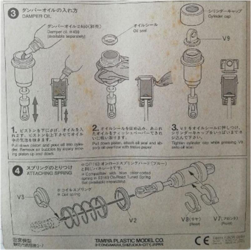
Construction manual for the four light‑alloy shock absorbers, part number 53280, designed for the TA03 chassis and also perfectly suitable for the TA01, TA02, TL01 and TA04 series.
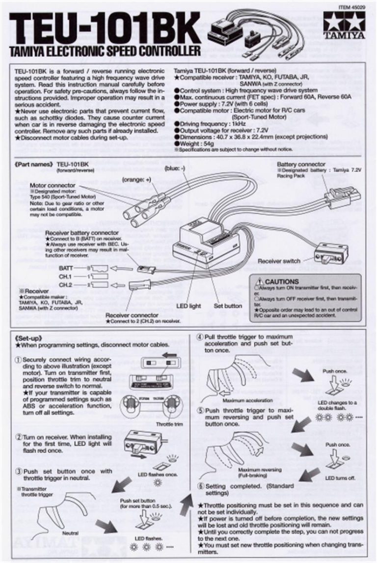
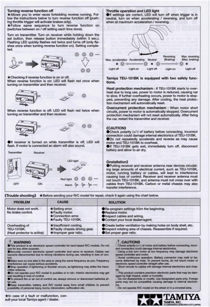
Configuration manual for the TEU‑101BK electronic speed controller.
Restoration of the chassis
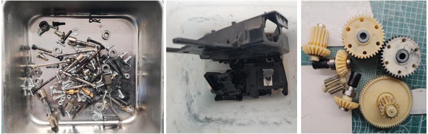
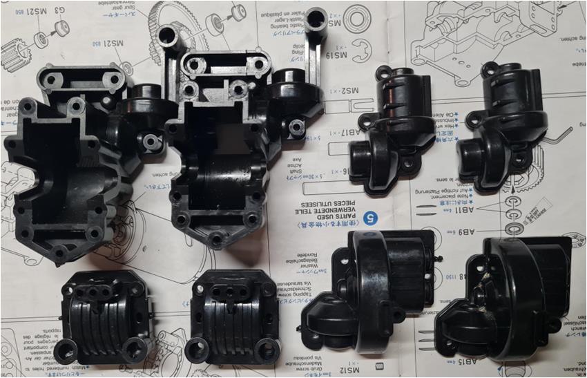
Every restoration begins from the same starting point: disassembling the chassis completely and separating the parts by material. The small hardware and metal components (image on the left) are treated with a diesel bath for one week. Diesel chemically attacks oxidation, rust and grease, reducing the marks left by time. It also leaves a thin oily film that protects the surfaces and makes them shine. The plastic parts (image in the center) are washed with hot water and dish soap; a toothbrush helps reach the most hidden areas. The gears (image on the right) are in excellent condition and show no signs of wear. A generous amount of grease had been used. The excess grease is removed with a kitchen paper towel. No further work is required and all bushings have already been replaced with equivalent ball bearings. The four wheels are washed with warm water and soap to remove the most visible traces of mud; the intention is not to remove all marks left by the terrain, as they make the condition of the wheels more authentic.
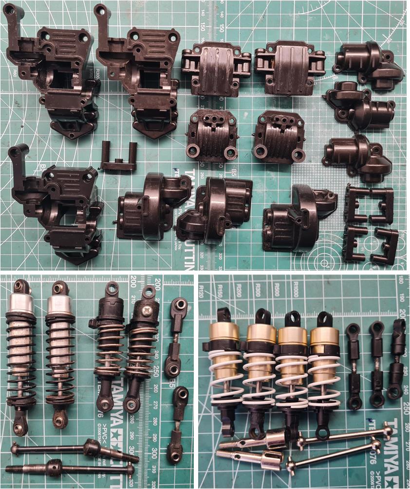
After this treatment, all parts are ready to be inspected; non‑original and damaged components must be replaced with new ones. For this purpose, spare black plastic parts are available (image in the first row), although in reality only the chassis tub shows significant wear; the other pieces are in good condition. The shock absorbers, three steering tie rods (one is missing) and the front axles are not original (image on the left of the second row), so they are replaced with equivalent original parts (image on the right of the second row). These discrepancies were already evident from the initial visual inspection of the chassis. No additional inconsistencies were found, except for the presence of two planetary‑gear differentials. The manual specifies one ball differential and one gear differential; the rear one is replaced with an equivalent ball differential, part number 53070, described as “Manta Ray Ball Differential”..
After careful inspection, the plastic parts that were replaced are the following: A2, A3, A5 and B6.
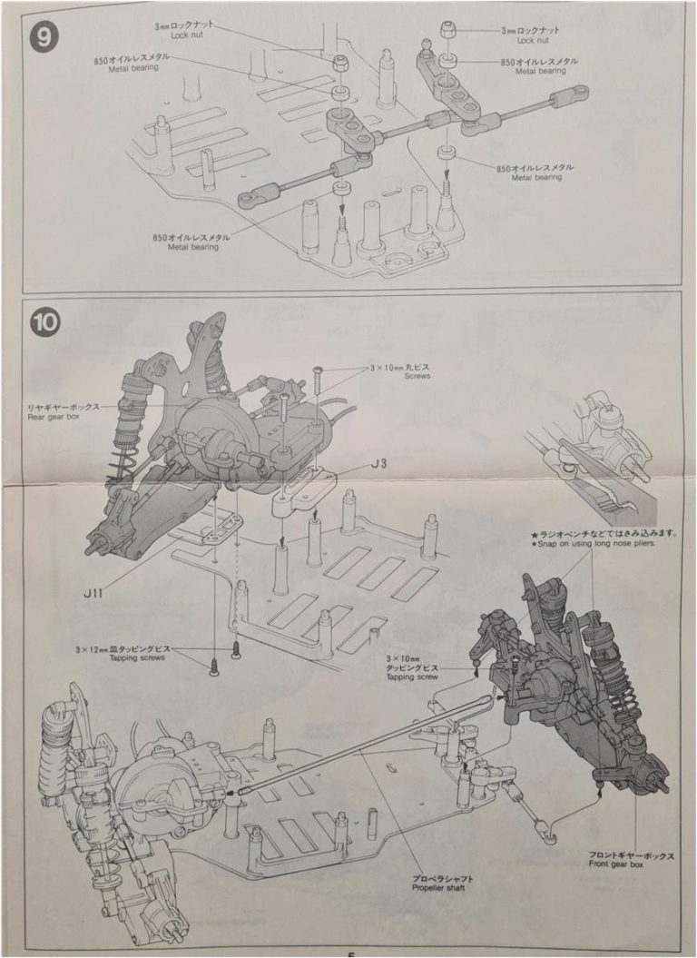
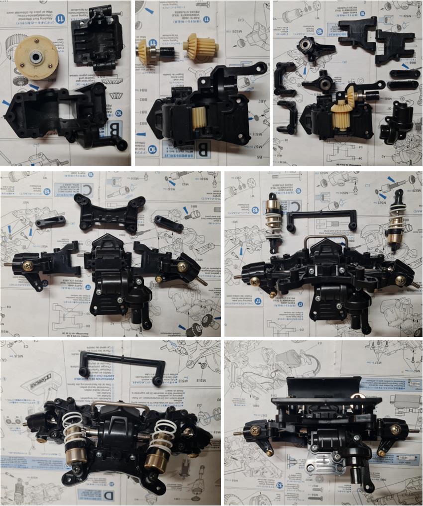
The construction of the front section includes the suspension system, the steering assembly and the differential housing. All bushings have been replaced with ball bearings. The one‑piece front axles included in the lot are an aftermarket accessory not listed among the original parts for this model; they do not appear to be genuine Tamiya components and are likely from Yeah Racing. For this reason, they were replaced with original axles and hubs. The non‑original shock absorbers found in the lot were replaced with the dampers from set number 58280. In the image on the right of the second row, the U‑shaped body mount can be seen, a part unique to this model. The FRP plate, part number 53193, was not installed to support the shock absorbers; no suitable method was found to properly secure the upper suspension arm to the plate. The arm must be able to rotate, but without any play in the joint; excessive movement compromises handling, so the original plastic plate supplied in the kit was chosen instead. The final step is attaching the front bumper, which is made of a softer plastic than the other components so it can flex and absorb frontal impacts.
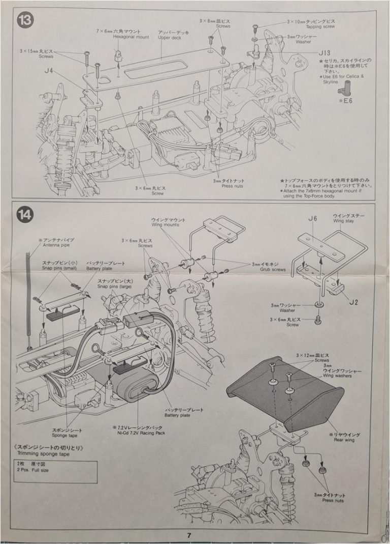
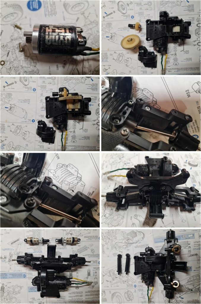
The construction of the rear section includes the suspension system, the motor assembly and the differential housing. All bushings have been replaced with ball bearings. The circular plastic motor plate has been replaced with the equivalent light‑alloy version, part number 53142. The non‑original shock absorbers found in the lot were replaced with the dampers from set number 58280. In the image on the right of the last row, the two body posts used to connect the body shell to the chassis can be seen; these supports are unique to this model. The FRP plate, part number 53194, was not installed to support the shock absorbers for the same reason the FRP plate was not used in the front section. The final step is attaching the rear impact guard.
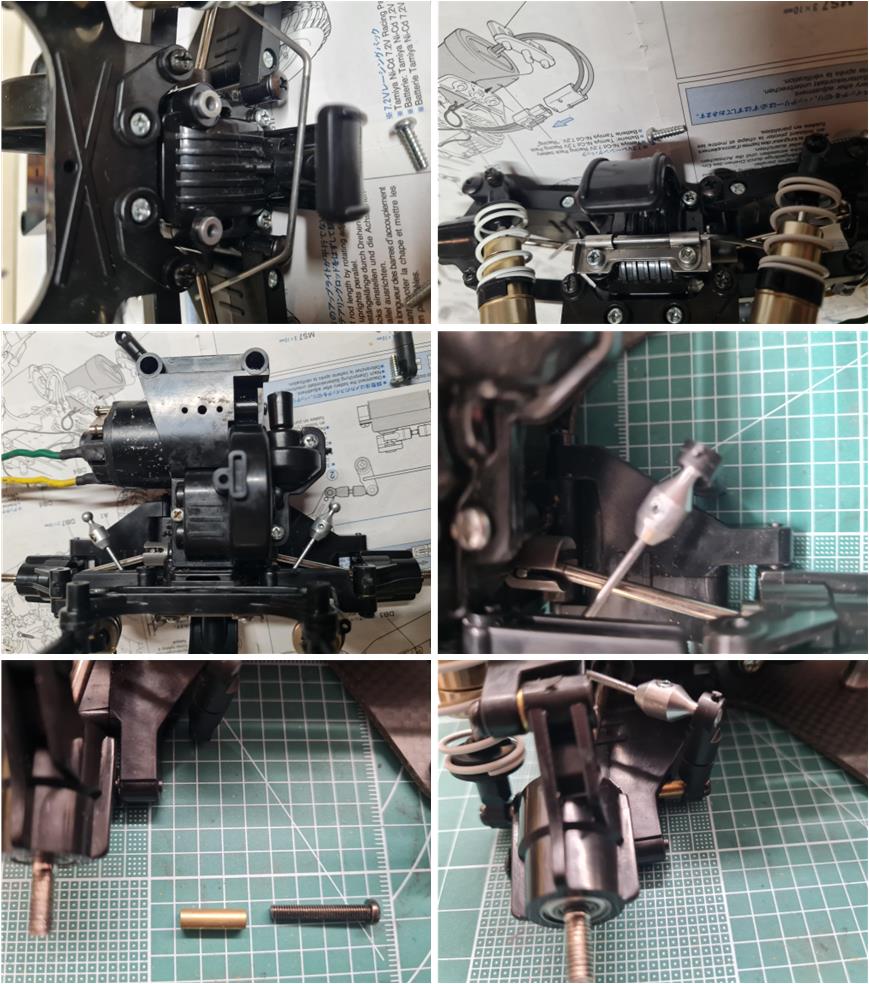
The rear anti‑roll bar, part number 53189 and described as “4WD touring and rally car rear stabiliser set for TA02 chassis,” was designed for the TA02 chassis and cannot be installed on the 260 mm‑wheelbase TA01 without modifications. The 280 mm TA01 chassis uses suspension arms similar to those of the TL01 or M02 chassis: the lower arms are made of two separate pieces. For this reason, it is possible to replicate the solution used with set 53324 for the TL‑01 chassis. At the rear, the stabiliser bar is mounted to the chassis in the same way as on the TA02 (images in the first row). At the front end of the bar, proceed as done for the TL‑01 stabiliser: replace the screw that joins the two parts of the lower suspension arm with a longer screw and a spacer (image on the left of the last row). Then the stabiliser arm can be connected to the suspension as shown in the image on the right of the last row.
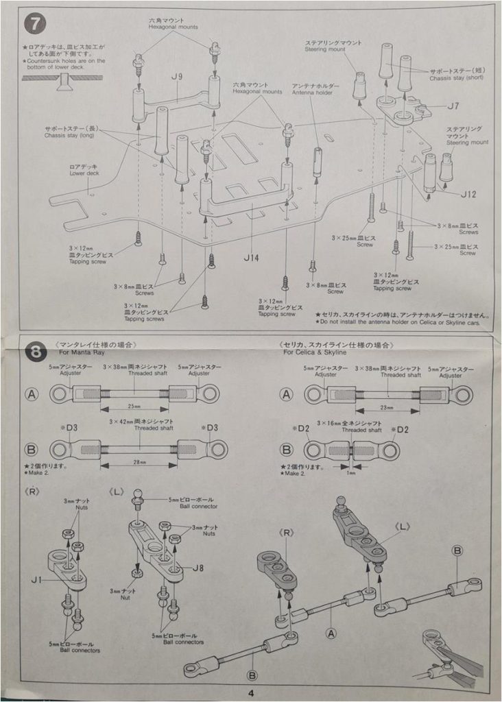
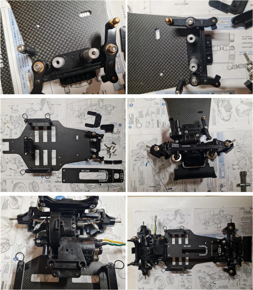
When the front and rear sections are assembled, the chassis can be completed with the central double‑deck carbon‑fiber plate. The four bushings of the steering levers are replaced with 850‑size ball bearings (image in the first row). First, assemble the lower central plate to the front section, then to the rear section; finally, install the upper plate.
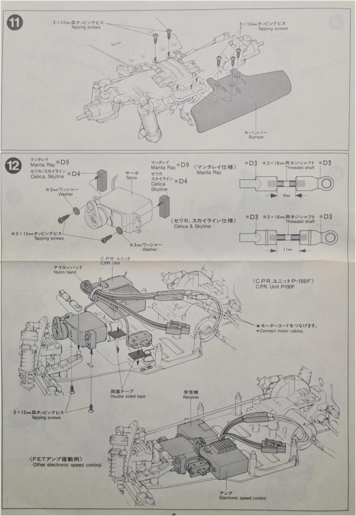
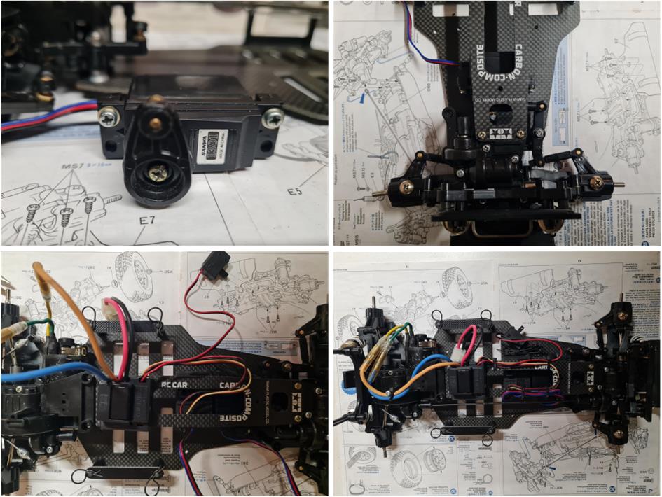
The electrical system consists of the steering servo (images in the first row), the receiver and the electronic speed controller. The cables are secured to the upper chassis plate using black plastic zip ties.
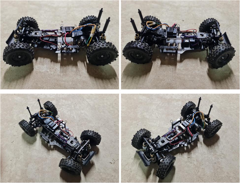
Images of the complete chassis with wheels and rims, ready to receive the body shell.
Body shell The only operation that seems necessary is washing it with hot water, as there are light traces of mud, although these marks actually make the body shell look even more authentic. It must be evaluated whether to wash the body shell or not in order to avoid removing this patina, so as a first attempt the body shell is not washed too vigorously: the goal is to leave some subtle traces of mud. The only required mechanical operation is removing the double‑sided tape on the inside under the hood (image on the right of the last row).
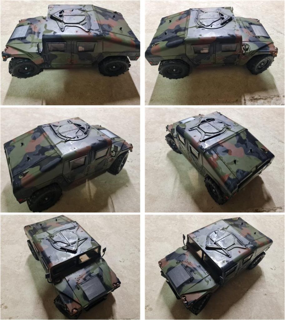
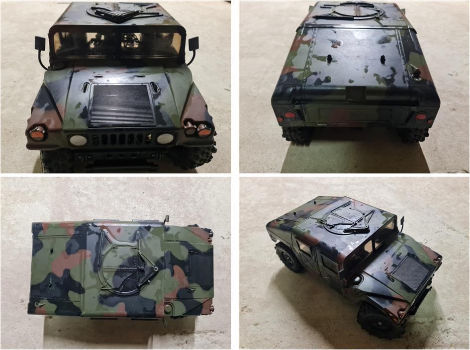
Restored model Images showing the completed model.
Tamiya, original figure, box art, guide book and catalogue are of TAMIYA INC, which does not endose or sponsor www.tamiyaclassic.com. Any brands, logos and trademarks represented on this website are the copyright of their respective owners.