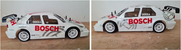
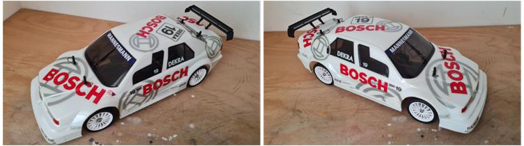
Alfa Romeo 155 V6 TI Bosch

Model

Tamiya Alfa Romeo 155 V6 TI Bosch, item number 58195, released for sale in 1997 and available on the market until 2001.
Lexan bodywork.
TL-01 chassis.

Analysis of the model to be restored

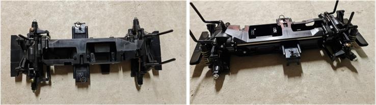
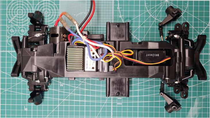
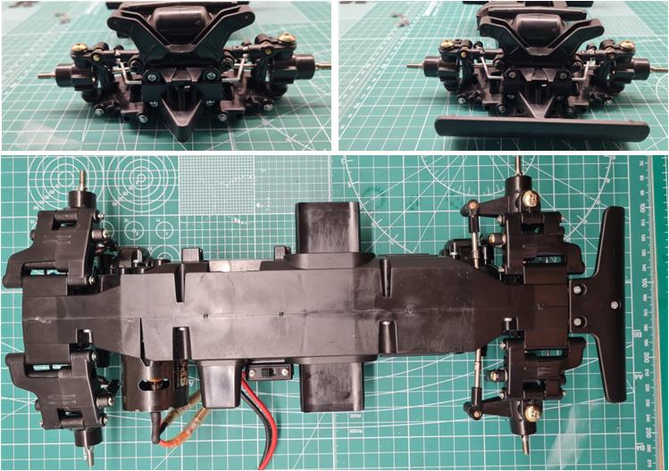
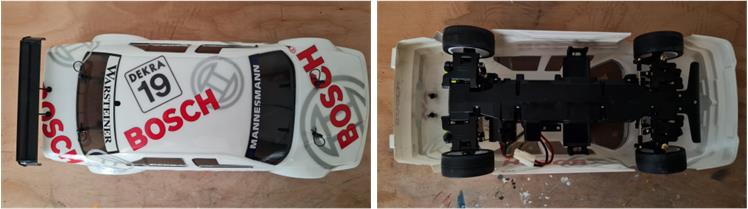
This project began because a TL-01 chassis was sold together with the Bull Head chassis. The TL-01 chassis is assembled and intact; from an initial analysis, it shows no signs of wear from contact with the track.

Starting from the front and moving towards the rear, the chassis analysis reveals that:

– the front and rear bumpers are those of the TL-01 model,
– the front and rear suspensions are those of the TL-01 model,
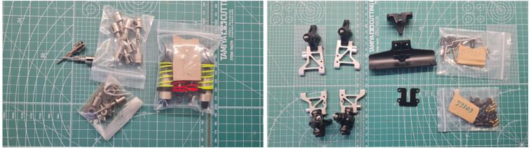
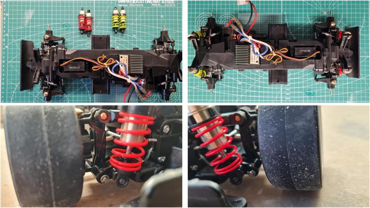
– the four spring shock absorbers included in the basic setup are present,
– the upper suspension arms and steering arms are the non-adjustable ones provided in the basic setup,
– the four body mount towers are present and have not been cut to fit a body shell.

In the absence of additional photos, it is not possible to determine the condition of the chassis underside, but the visible parts appear flawless—giving the impression that they have never been used on track.
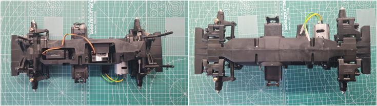
Upon arrival of the model and after an initial analysis, the complete absence of scratches on both the upper and lower parts can be confirmed; all components seem freshly assembled, with no evident breakages. Only a few screws have been overtightened, causing cracks in the plastic (for example, see the left steering arm in the second photo below, viewed from underneath).
The model arrived complete with a motor, receiver and steering servo.

Not knowing which body shell is associated with this chassis and given the lack of significant differences between the various model chassis, it is possible to choose one of the body shells originally paired with the standard TL-01 chassis: Calsonic Skyline GT-R, Alfa Romeo 155 V6 TI Bosch, Toyota Celica GT-Four 1997 Monte Carlo, Peugeot 406 ST, Ford Escort WRC, Mitsubishi Lancer Evolution IV Monte Carlo, Ford SVT F-150 Lightning, Pennzoil Nismo GT-R, Subaru Impreza WRC, Ford Mustang Cobra, Castrol Mugen NSX, Lexus IS 200, Ford Focus WRC, Mercedes CLK-GTR Original-Teile, Lexus GS400, Calsonic Skyline GT-R R34, Mercedes-Benz CLK DTM 2000 Team D2, Opel V8 Coupe, Toyota Castrol Tom’s Supra 2000, Subaru Impreza WRC 2001, Porsche 911 GT3 Cup V.I.P., Nissan 350Z, Ferrari 360 Modena Challenge and Ford Focus RS WRC 200.

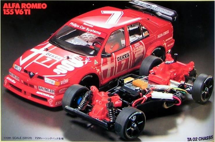
With two dozen alternatives, the choice fell on the Alfa Romeo 155 V6 TI Bosch body shell, as the four-wheel-drive TL-01 chassis resembles the full-scale model. Additionally, this chassis, along with its body shell, will complement the special edition Alfa Romeo 155 V6 TI autographed TV SpielFilm model, featuring the TA-02 chassis, item number 58128.

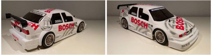
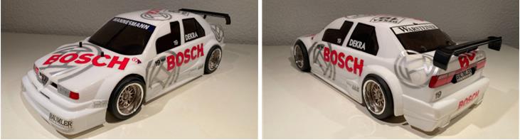
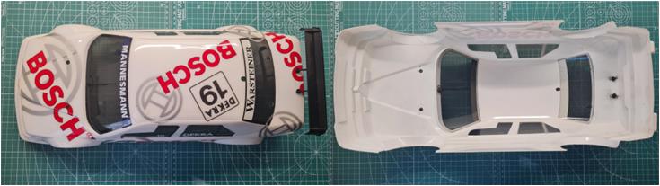
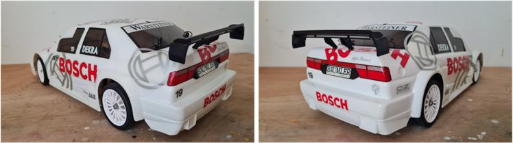
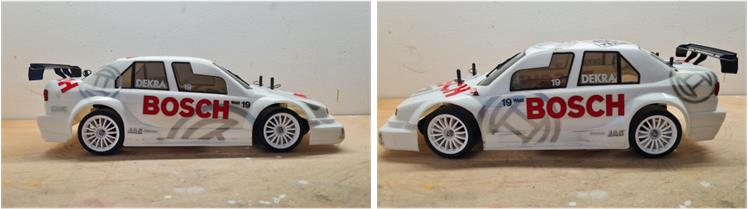
Body shells for the TL-01 chassis are readily available in 2025 and the first seemingly intact one was selected. Starting from the front and moving towards the rear, the body shell analysis reveals that:

– the stickers are correctly positioned,
– the windshield wiper is present and intact,
– the rear spoiler is present and intact.

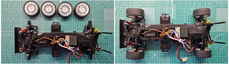
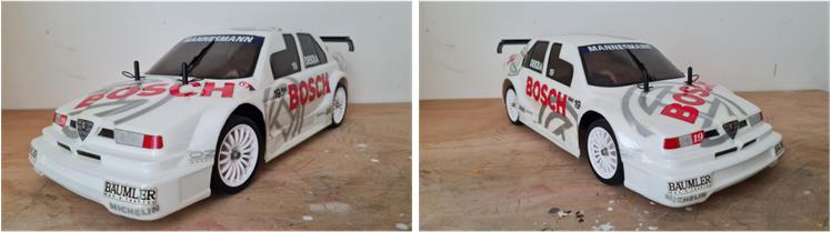
The rims shown in the photo are not part of the offer. When the body shell arrived, both external and internal analysis confirmed that it is in excellent condition.

Restoration

The TL-01x chassis, in its four versions, dominates the numbering range from 58200 to 58299, representing almost one-third of the models. For this reason, in 2025, there is an abundant availability of spare parts and special components. The decision has been made to disassemble, overhaul and rebuild this chassis, equipping it with some accessories to enhance performance. For this project, the following components are available:

– low-friction shock absorbers, set number 53280,
– front stabilizer bar, set number 53324,
– rear stabilizer bar, set number 53324,
– adjustable upper suspension arms, set number 53303,
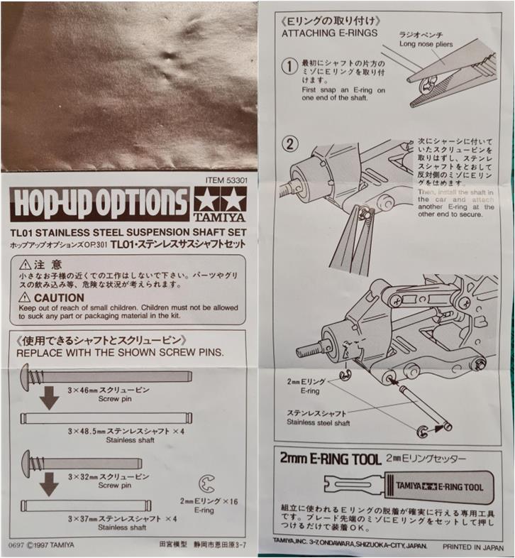
– aluminum suspension shafts, set number 53301,
– adjustable steering arms, set number 53300.

The market has made various types of aluminum lower suspension arms available. However, installing a stabilizer bar on these suspensions can often be challenging if the manufacturer has not provided for it. The set found on the market lacks mounts for the stabilizer bars, which is why the installation of aluminum lower arms will be reassessed during reconstruction—the choice being between stabilizer bars and aluminum lower arms. Additionally, the front bumper with its triangular mounting system from the TL-01B buggy chassis is available (these two pieces are part of code 10005688, described as “C-Parts TL-01B / WR-01 / WT-01”). This solution is also ideal for the road version, replacing the “duckbill” bumper typical of the TL-01 model. The TL-01B version bumper provides better protection against frontal impacts. At the rear, the F.R.P. plate from the TL-01LA and TL-01B chassis is available, replacing the rear bumper, which is identical to the “duckbill” front bumper.
When working on refurbishing a plastic chassis, there is often a risk of finding cracked screw mounts and no repair can truly fix them—the damaged part must be replaced.

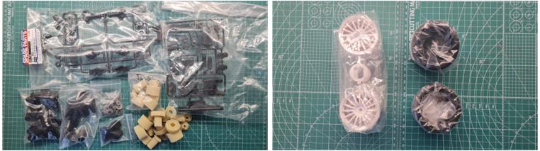
For this reason, many spare parts have been gathered, including:
– Part A, code number 50735,
– Part B, code number 50736,
– Part C, code number 50737,
– some servo savers,
– many rear hubs,
– several sets of gears.

The purchase lot lacked rims and tires entirely, but these were found on the spare parts market:
– Tires, code number 50454, described as “Racing Slick Tires 2 pcs,”
– Rims, code number 50678, described as “Tom’s Exiv Jtcc Wheels 2 pcs.”

At the time, Tamiya released the carbon shaft for the front-to-rear gearbox transmission, code number 53323. Today, this part is nearly impossible to find, but it provides a significant performance boost due to its much lighter weight.
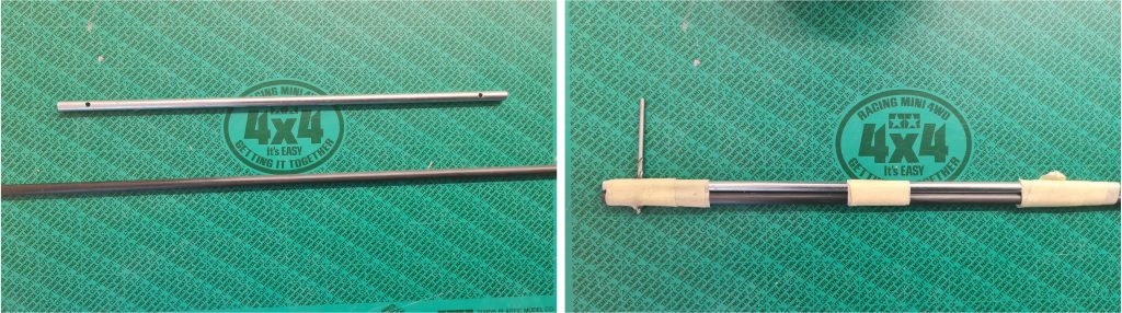
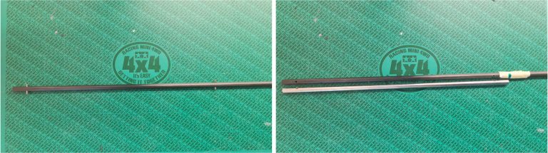
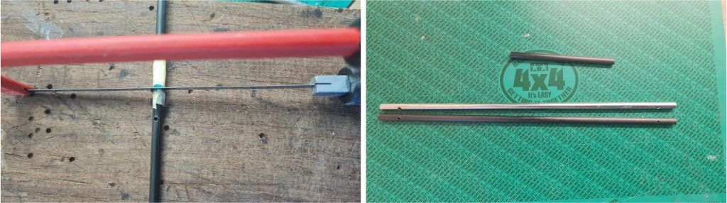
It is possible to fabricate this shaft starting from a solid 5 mm diameter carbon fiber tube, using the standard metal shaft as a reference. Note: Working with carbon fiber releases a large amount of fine dust, so all necessary precautions should be taken as it is hazardous to health. Step-by-step image sequence demonstrating the construction of the carbon shaft:

– The carbon shaft must be solid and not hollow; otherwise, it will not provide sufficient strength and will break under normal use. Secure the metal shaft to the carbon shaft using masking tape so that the two ends align (see the right-side photo below). Attach the two parts at least in three spots, ensuring that the metal shaft has holes for the gear pins perpendicular to the carbon shaft.
– The holes for the gear pins perpendicular to the carbon shaft will serve as guides for the 2 mm metal drill bit.

– Drill both ends using the existing holes in the metal shaft as a guide.
– Test that the gear pins fit perfectly into the two holes.
– Position the metal shaft and the carbon shaft so that their ends align (see the bottom right image).
– Apply masking tape to the carbon shaft near the point where both shafts have the same length.
– Mark the exact point with a marker where the carbon shaft should be cut to match the length of the metal shaft.

– Cut the carbon shaft using a metal saw.
– Compare the carbon shaft with the metal shaft; in the bottom right photo, you can also see the unused portion.

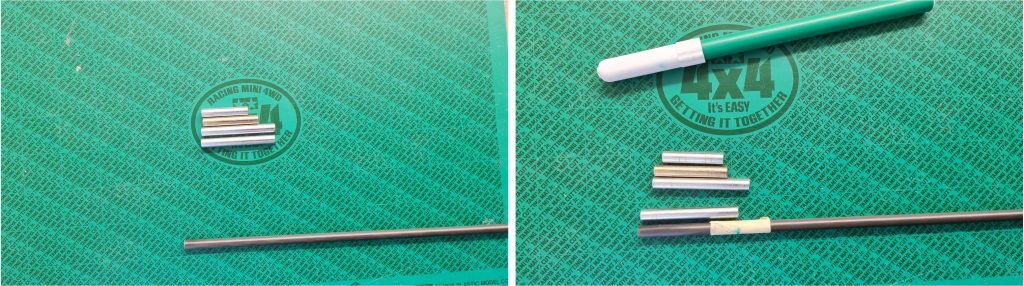
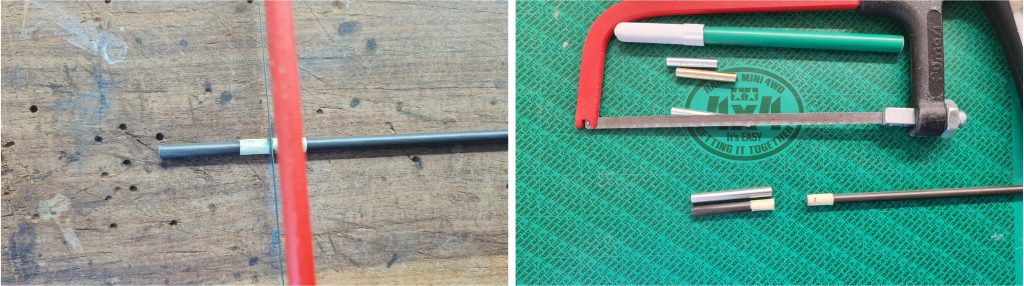
At the time, Tamiya released a set consisting of four carbon shafts: two measuring 40 mm, one 35 mm and one 25 mm. These four shafts were installed in the front-to-rear gearbox housings, code number 53322. This part is now extremely difficult to find, but it significantly improves performance due to its lighter weight. It is possible to fabricate the four shafts using a carbon fiber tube with an outer diameter of 5 mm and an inner diameter of 3 mm, using the standard metal parts as reference samples. Note: Working with carbon fiber generates a significant amount of fine dust, so all necessary precautions must be taken, as it poses health risks. Step-by-step image sequence demonstrating the construction of the 40 mm carbon shaft:

– Position the metal shaft and the carbon shaft so that their ends align (see the bottom right image).
– Apply masking tape to the carbon shaft near the point where both shafts have the same length.
– Mark the exact point with a marker where the carbon tube should be cut to match the length of the metal shaft.

– Cut the carbon tube using a metal saw.
– Compare the carbon shaft with the metal shaft; in the photo, you can also see the unused portion, which is perfect for making the other three shafts.

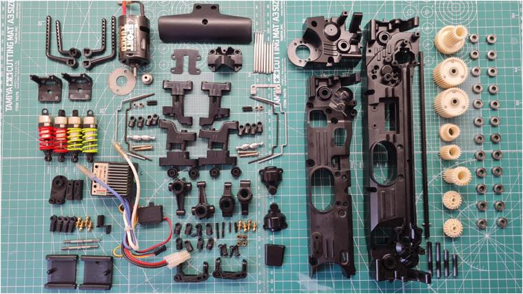
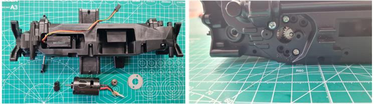
Replicate the same sequence for the second 40 mm shaft, the 35 mm shaft and the 25 mm shaft. To enhance performance, the standard motor has been replaced with a Sport Tuned motor, the HITEC SP 520 electronic speed controller has taken the place of the mechanical speed control and the bushings have been replaced with 1150-sized ball bearings. The image below displays all the parts ready for installation.

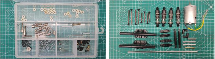
In the two photos below, you can see the parts that have been replaced, excluding the small hardware, which is being reused. These parts are stored with the model so that, in the future, it will be possible to revert to the factory configuration.

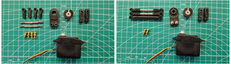
With all the stock parts and performance upgrades gathered, it’s time to begin assembling the chassis. Following the instructions, the process starts with the steering system, where the fixed right and left arms have been replaced with the adjustable version, set number 53300. In the image, you can see how the two adjustable arms have the same extension as the non-adjustable one.

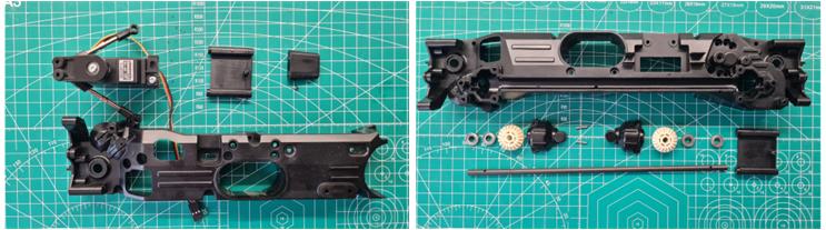
The next step is assembling the custom-built carbon axle with the four bearings and the two bevel gears. The parts fit perfectly, proving that the carbon axle is an accurate replica of the original.

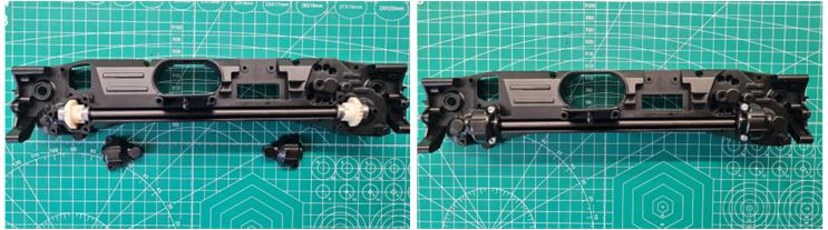
The final verification of the work done on the transmission axle is the installation of the axle itself into the chassis. The parts fit together perfectly.

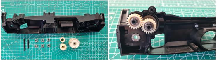
The instruction manual outlines the assembly of the front gearbox housing.

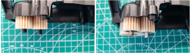
To verify the precise execution of the custom-built 40 mm and 35 mm carbon shafts, you can compare the two photos below. On the left, the carbon shafts have been installed, while on the right, the metal ones are shown. There is no visible difference and the parts fit perfectly.

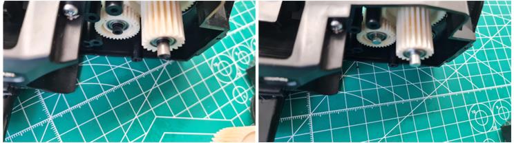
Perform the same operation with the rear axles, comparing the carbon and metal versions. There are no differences and the installation is completed quickly.

With the three chassis components assembled, it’s time to install the electric motor. The chosen setup includes a 21-tooth pinion gear.

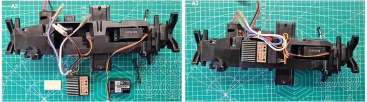
Now it’s time to install the electronics, including the receiver, the Acoms servo and the Hitec electronic speed controller.

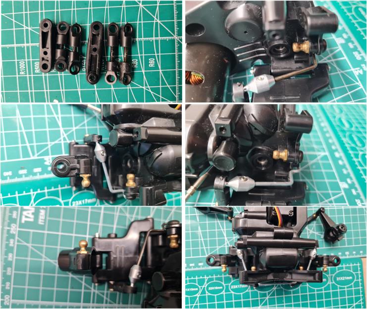
The next step is assembling the suspension system, which is the focal point of the technical upgrades. The metal lower suspension arms were discarded because they do not allow for the installation of stabilizer bars. The suspension system has been built following the TL-01 chassis instructions, incorporating aluminum suspension shafts from set number 53301 and two stabilizer bars from set 53324. 

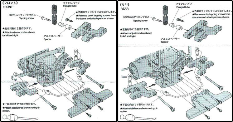
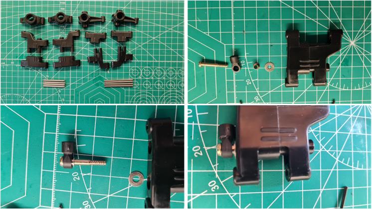
From the manual of set 53324 “stabilizer bars,” the use of the aluminum cylinder “spacer” is evident. However, this part is not available among those I was able to find and has been replaced by a washer, as shown in the images below. This modification was also made when the TL-01 chassis was in production to lighten (even if only slightly) the suspension arms.

Now the stabilizer bars can be assembled along with the four suspension arms.

It’s time to secure the arms to the chassis using the aluminum suspension shafts from set number 53301. In this case, the installation manual is available.

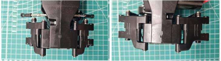
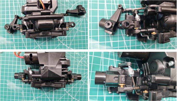
The images below show the front suspension (on the left) and the rear suspension (on the right).

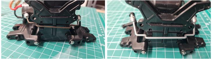
The images below illustrate the stabilizer bar arms and how they interact with the suspension system.

This setup ensures optimal chassis balance—installing the stiffer stabilizer bar at the front (silver-colored) enhances handling through mixed sections, while placing the softer stabilizer bar at the rear (black-colored) maintains solid traction when exiting corners. 

The top-down view of the chassis provides a complete perspective of the layout and assembly, showcasing the integration of suspension components, stabilizer bars and the upgraded drivetrain. 

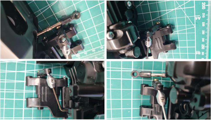
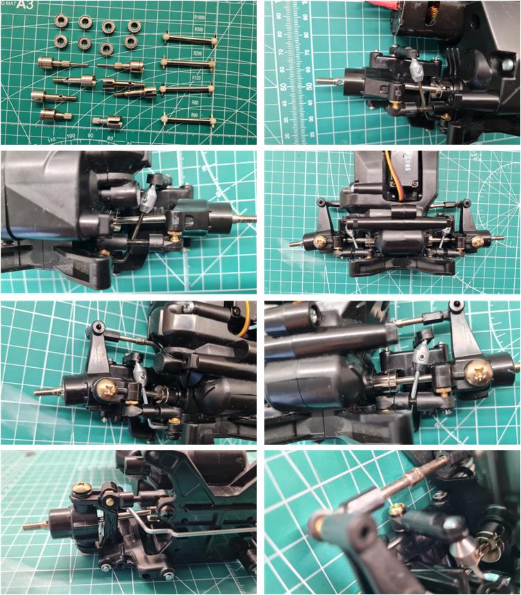
To adjust the length of the upper suspension arms (set number 53303), use the front and rear upper arms as reference samples—see the first photo in the top left. Each suspension features a pair of ball joints: one installed on the central chassis and the other mounted on the hub. This setup ensures precise alignment and optimal suspension performance.

To verify the correct length of the upper arms, proceed with the full installation. Once assembled, ensure that the suspension movement is smooth and unrestricted—this confirms proper alignment. If adjustments are needed, fine-tune the threaded sections to match the original reference arms.

To finalize the mechanical assembly of the chassis, install the four bearings into the hubs, followed by the four axles and wheel pins. With this step completed, the entire drivetrain and suspension system are securely in place, ensuring smooth movement and improved efficiency.

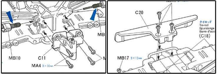
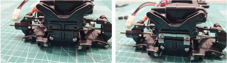
The TL-01B version bumper has been selected for installation, identifiable by its triangular bracket and its shape, which is more efficient than the factory “duckbill” design.

Excerpt from the manual for the installation of the bumper on the TL-01B chassis.

For the same reason, the F.R.P plate has been installed at the rear, as it comes standard on the TL-01B and TL-01LA chassis.

The suspension assembly is completed with the installation of low-friction dampers. Ball joints have been installed on both the chassis and suspension arms.

In Tamiya spring sets, stiffness is defined by color:
– Red springs are soft
– Yellow springs are medium
– Blue springs are hard
– White springs are extra hard

To enhance traction and handling, the chosen setup features soft front springs and slightly stiffer rear springs for optimal balance.

Now it’s time to install the four tires and rims.

Body restoration
There is nothing to restore in the body, just wipe off dust.
To date (2024) Tamiya has released these models over the years:

main sponsor Alfa Romeo with red body with carbon fiber chassis TA-02, model number 58128,
– main sponsor Alfa Romeo with red body with plastic bathtub chassis TA-02 model number 58128,
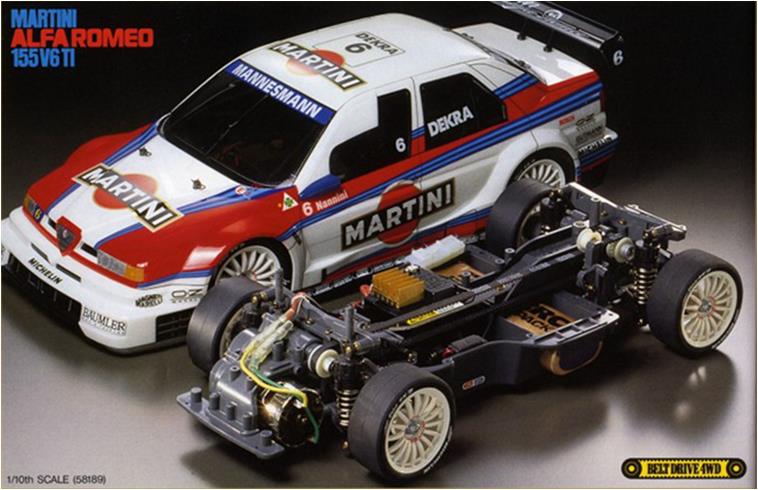
main sponsor Martini Racing with white coloured body available with chassis TA-03F model number 58189,
– main sponsor Bosch with light grey coloured body with chassis TL-01 model number 58195,
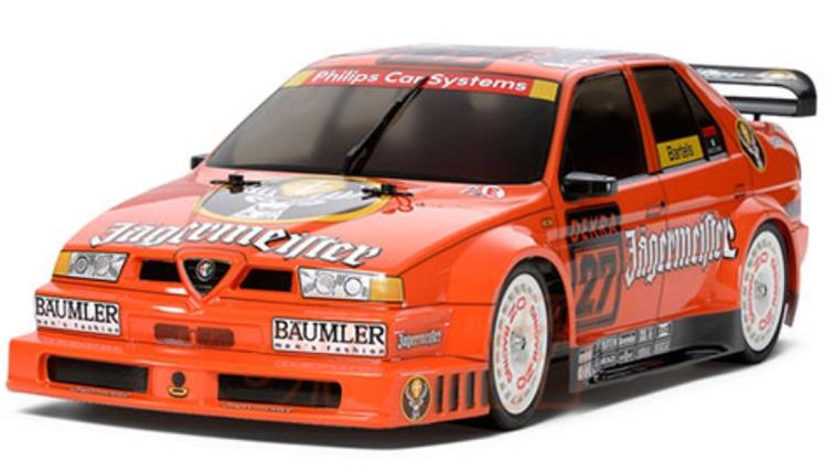
main sponsor Jagermeister with orange coloured body with chassis TT-02 model number 58585,
– main sponsor Martini Racing with white coloured body available with chassis TT-02 model number 58606,
– main sponsor Spielfilm TV with dark orange body by Carson number code 68977

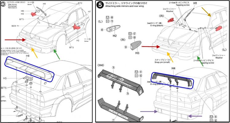
There are two different bodys for the Alfa 155 V6 TI: the first body was used on the red Alfa Romeo and the Jagermeister model and the second body was used on the Alfa Martini and Bosch model. In the image below are excerpts from the body instructions: on the left the first version and on the right the second version. In racing on fast tracks, the biggest problem for Alfa Romeo is poor aerodynamic penetration, which penalises top speed, so Alfa Romeo evolved the body to improve the aerodynamic efficiency of the Alfa 155, which is basically a comfortable middle-class saloon that struggles to compete against coupes like the Opel Calibra that have better aerodynamics and lower ground clearance.
The two bodies differ in:

– the shape of the front pillar of the front side windows on the driver’s side and the passenger side (see brown arrow in the second picture on the right). In the second version there is a deflector which has an aerodynamic function to improve the Alfa 155’s penetration coefficient; top speed was one of the points where it lost out to the low Mercedes 190 EVOII and then to the Opel Calibra which was a coupe with better aerodynamics,
– the shape of the rear-view mirrors (highlighted in red in both the picture on the right and the picture on the left),

– the shape of the lower air intake on the front bumper (highlighted with an orange arrow both in the picture on the right and in the picture on the left) and the small air intake under the logo on the front (highlighted in dark red both in the picture on the right and in the picture on the left)
– the shape of the engine exhausts on the rear bumper which are only present in the second version (double purple arrow on the right in the picture) and
– the shape of the rear spoiler (see the two blue boxes in both the image on the right and the image on the left).

Restored model
Images showing the finished model.

Tamiya, original figure, box art, guide book and catalogue are of TAMIYA INC, which does not endose or sponsor www.tamiyaclassic.com. Any brands, logos and trademarks represented on this website are the copyright of their respective owners.