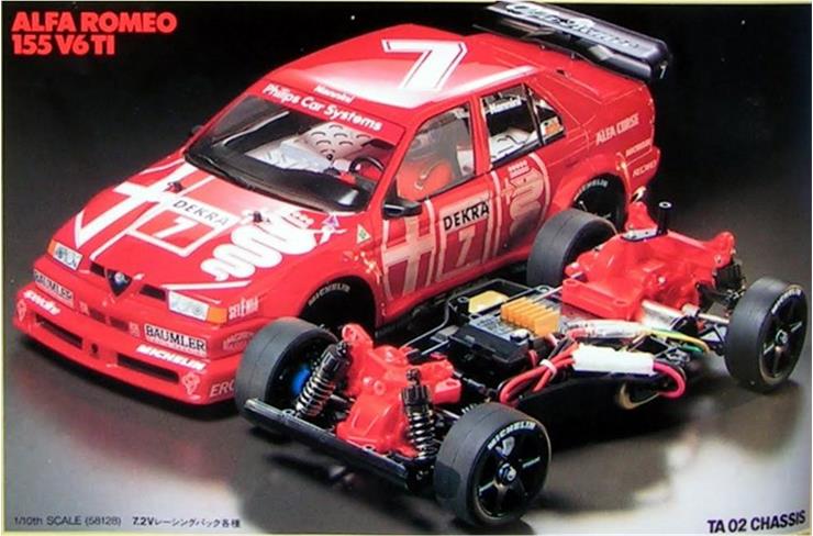
Model Tamiya Alfa Romeo 155 V6 TI, model number 58128, released in 1993 and available on the market until 1996 Lexan body; rear wing, centrally mounted front windshield wiper, driver’s side mirror and passenger’s side mirror in black styrene TA-02 chassis
Project Several parts are available, sourced from the market at different times and in different ways. Some parts were purchased new, others remained unused after previous restorations, others were bought used on well‑known online auction sites List of new parts:
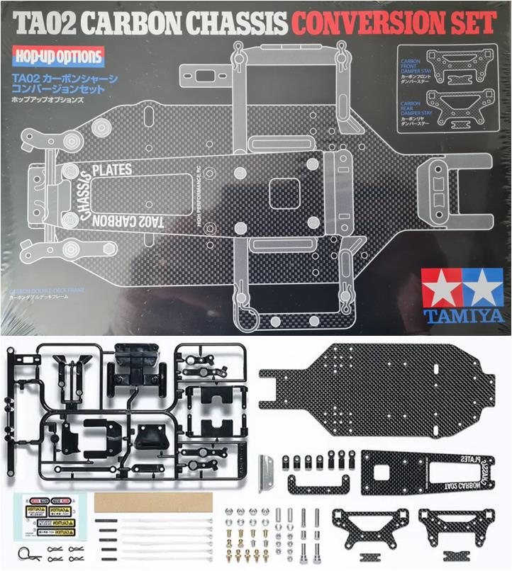
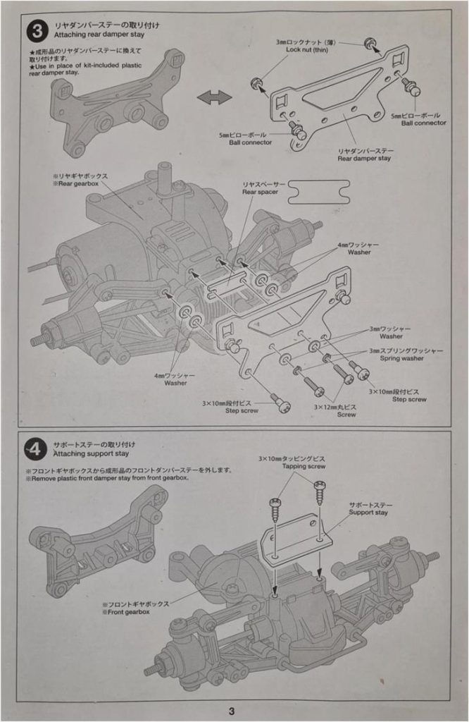
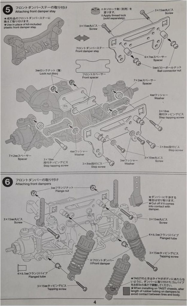
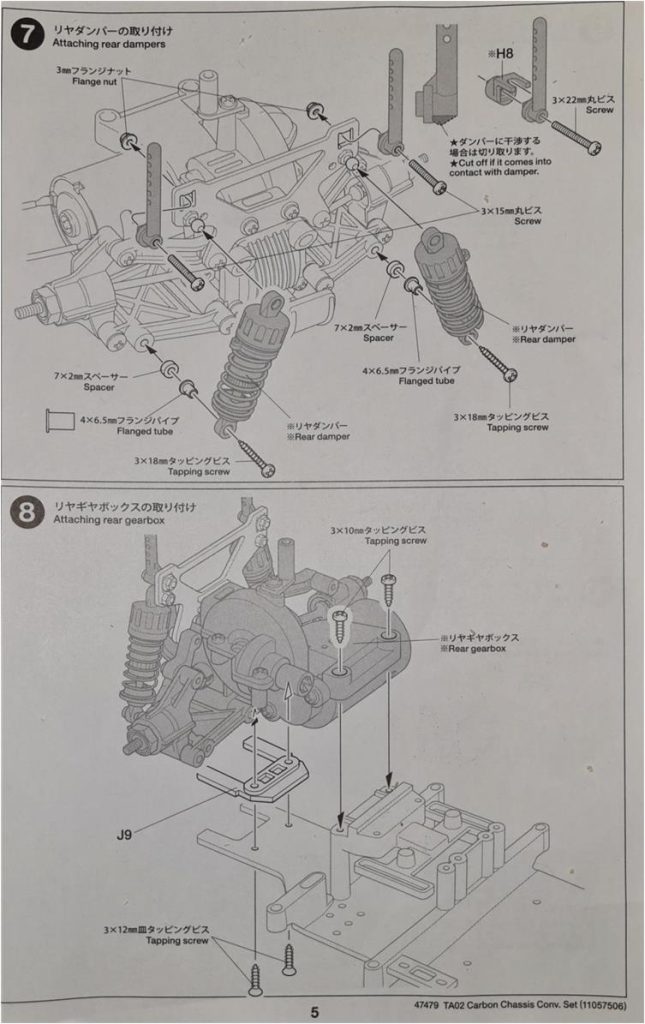
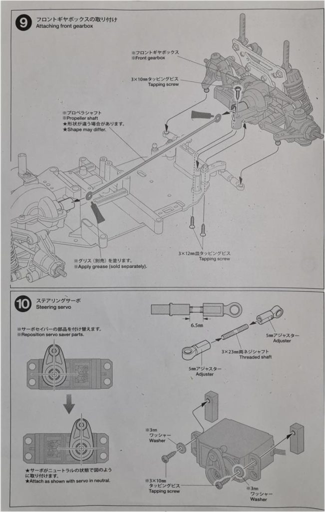
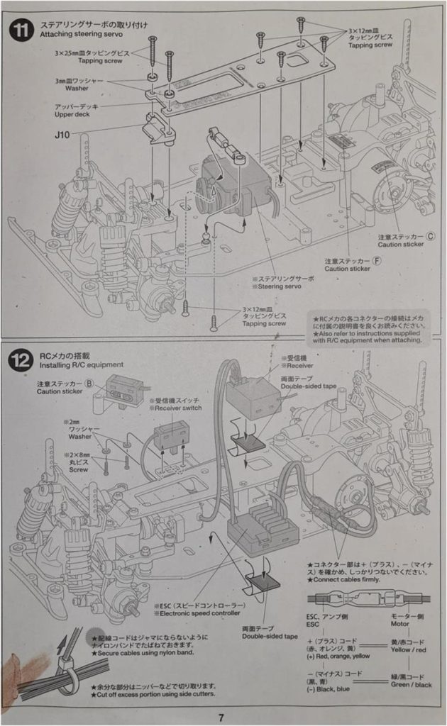
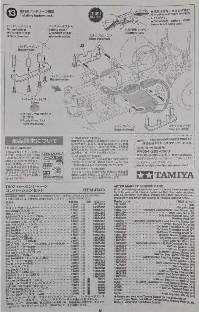
– Set number 47479, which includes the double carbon chassis, carbon front shock tower, carbon rear shock tower and all components needed to convert the plastic chassis into a carbon‑fiber chassis
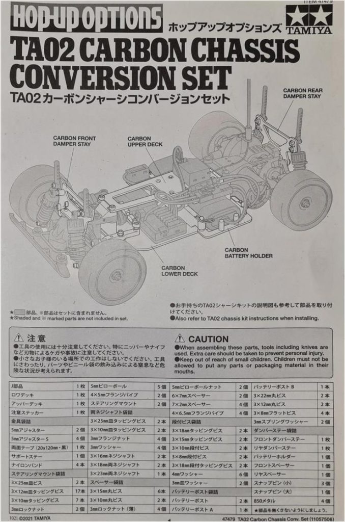
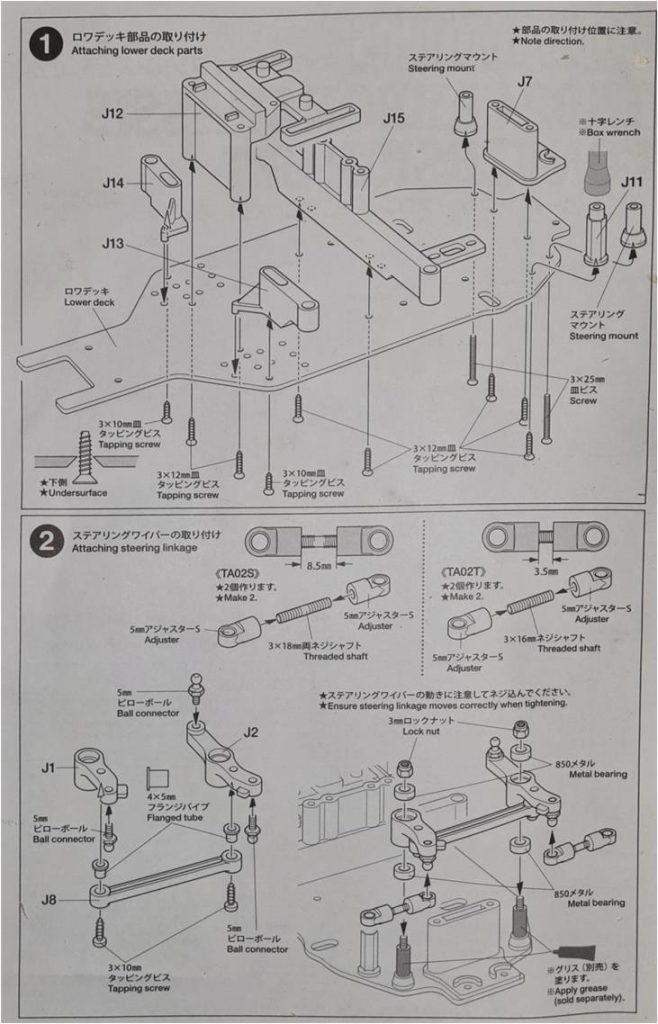
This set makes it possible to completely transform the appearance of the car, switching from the plastic tub chassis to a double carbon‑fiber chassis. Below are the images of the instructions.
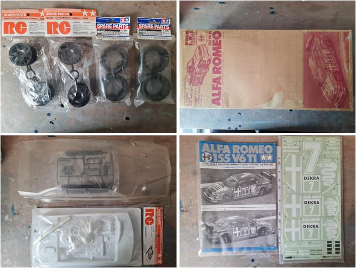
– new Alfa Romeo 155 body shell from the official team that raced in the 1993 German DTM championship, item number 50511 described as “Alfa Romeo 155 V6TI Body”. The packaging is in very poor condition, while the contents are in perfect condition. In addition to the body shell, the styrene accessories are included (front wiper, right mirror, left mirror and rear spoiler) and the decal sheet. – cockpit set for touring cars, item number 50457 described as “Mercedes AMG 190E (58108) – Cockpit Set – RC – 1:10”. – six‑spoke black plastic wheels, item number 50512 described as “Alfa Romeo 155 Wheels (2 pcs)”. The tyres to be mounted on these wheels are the semi‑slick racing version, item 50810 described as “Racing semi-slick tyres (2 pcs)”. Each set includes two pieces; the model requires four. – instruction manual for model 58128.
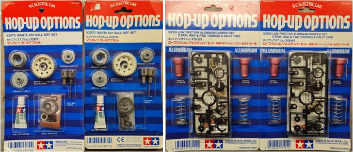
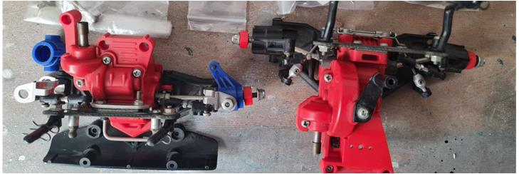
– ball differentials; item number 53070 described as “Manta Ray Ball Differential”. Two pieces available because it is not known which differential is installed in the starting chassis (on the left in the image) – high‑performance aluminium dampers; item number 53155 described as “Low Friction Aluminium Damper (2 pcs)” (on the right in the image). Each set includes two dampers; the model requires four: two for the front axle and two for the rear axle – aluminium motor mount, item number 53142 described as “4WD Rally & Touring Car Aluminium Motor Mount”
– complete set of ball bearings
List of non‑new parts:
– front and rear differential assemblies equipped with several accessories, such as the two carbon‑fiber shock towers. These two parts are already included in set 47479, so they will be set aside for future projects – completing the front system are the two one‑piece drive shafts, item number 53172 described as “TA02 and FWD car universal shaft set 1 pair”
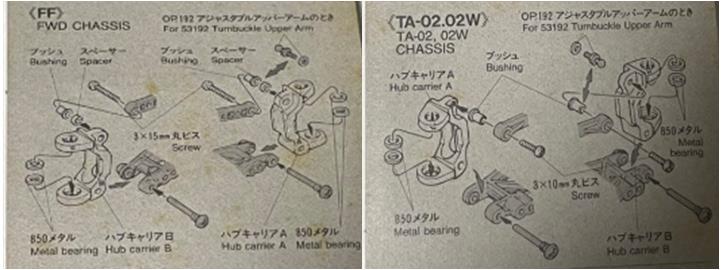
– the two C‑hubs of the steering system, item number 53226 described as “1/10 Touring Car Aluminium Front Hub Carrier (1 pair)”. This set can be installed both on FWD models (for chassis of the FF family) and on 4WD models (for chassis of the TA02 family), with slight differences in the components used.
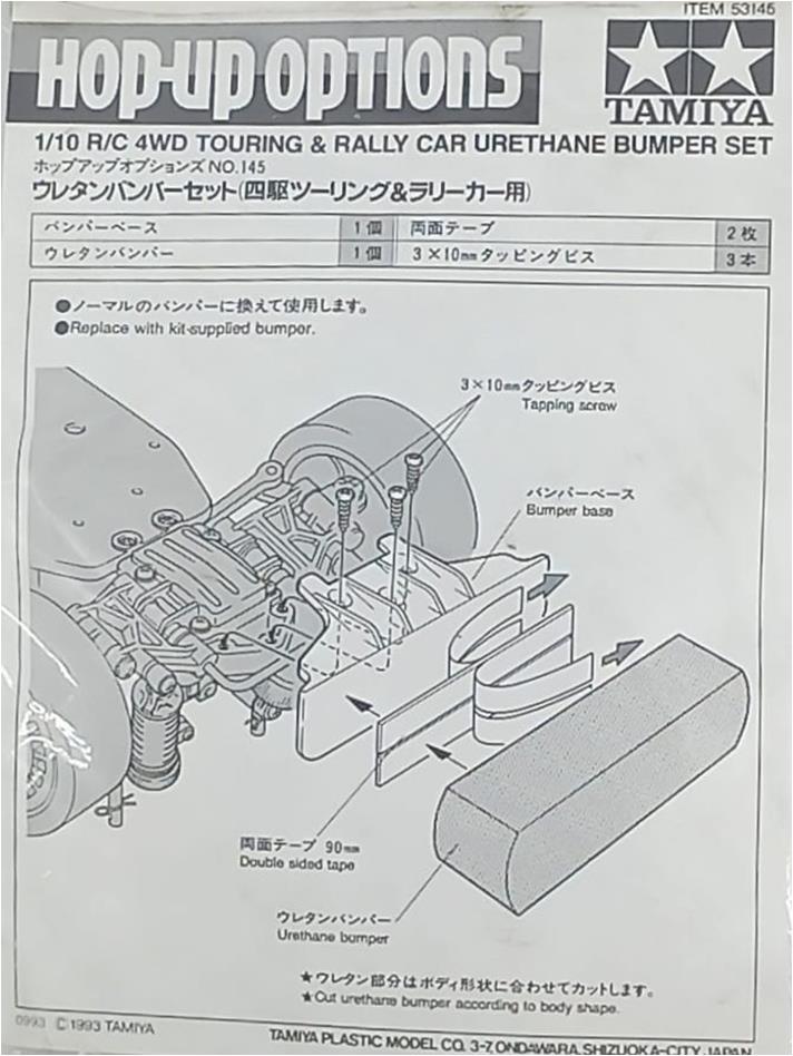
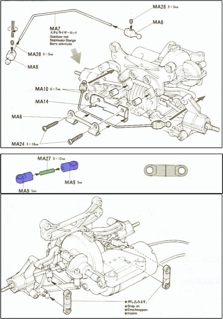
– rear anti‑roll bar, item number 53189 described as “4WD touring and rally car rear stabilizer set for TA02 chassis” (on the left in the image) – adjustable upper suspension arms, item number 58192 described as “RC 4WD/FWD Upper Arm” – two mounts for installing the steering servo, item number 53596 described as “Aluminium Servo Stays (Short), (DT-04/TA03/TA04/TG10/TNS)” – front urethane bumper, item number 53145 described as “4WD Touring & Rally Car Urethane Bumper” (on the right in the image)
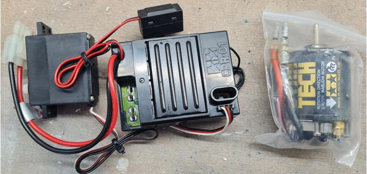
– complete electronics consisting of a two‑in‑one unit (receiver and speed controller) C.P.R. 01, TSU‑01 steering servo and electric motor item number 53001 described as “Dynatech 01R, 19T”
Chassis restoration
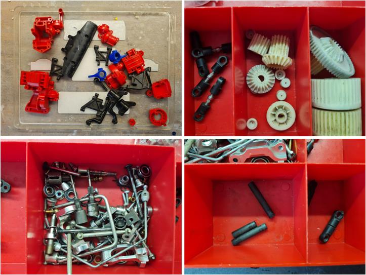
The first step is to assess the condition of the front and rear sections, which include the gearbox housing, suspension and steering system at the front and the electric motor assembly at the rear. Separate the various parts according to material and the treatment required for refurbishment: the upper‑left box in the first row of the left image for plastic parts and the lower‑left box in the second row of the left image for metal parts. When disassembling the two sections, it becomes clear that both differentials are the satellite‑gear type (right box in the first row of the left image), so they will be replaced with equivalent ball differentials, item number 53070. The three carbon shafts are present; they belong to item number 53164 described as “4WD touring & rally hollow carbon shaft”. Right box in the second row of the left image. The instructions for this set are shown in the right‑hand box. The gears appear to be new, almost completely free of grease and show no signs of wear.
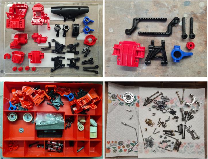
Metal parts are left in an airtight container filled with diesel fuel for one week; at the end of the treatment they are dried with a kitchen paper towel. After the process, the parts are coated with a thin film of oil that makes them shiny and protects them from oxidation (right image in the second row). No damaged parts were found. Plastic parts are restored using hot water and dish soap; after soaking the parts in a bucket with water and soap for one week, they are cleaned by brushing them with an old toothbrush. The goal is twofold: to clean the parts and to check for any cracks. At the end of the treatment several pieces were found that needed replacement. Starting from the top‑left corner and moving right, then down (right image in the first row): the four body posts are not the correct ones for the Alfa Romeo 155 DTM chassis, the lower half of the front gearbox housing (red part) shows several impact marks, one lower front suspension arm shows multiple impact marks, the steering knuckle (blue plastic) and one wheel hex have a deep crack. These parts are replaced with equivalent ones in better condition. In the left image of the first row, all plastic parts ready for assembly have been laid out.
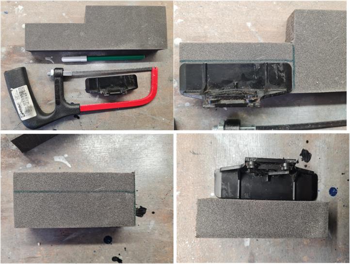
The front urethane bumper is made of two parts: a hard‑plastic support and a urethane foam impact block. The two parts are held together with double‑sided tape. The urethane impact block is missing and can be made from item number 53415 described as “Urethane Bumper Sponge For 1/10 Touring Car”. The foam can be cut using a standard metal hacksaw (top‑left image). The hard‑plastic part serves as a template for marking the cutting line with a marker (right image in the first row and left image in the second row). If the foam block is not perfectly sized, it can be shaped with 600‑grit sandpaper followed by 800‑grit (right image in the second row).
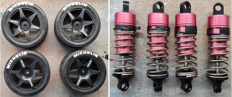
To prepare the wheels, the semi‑slick tyres must be mounted on the rims. Apply the Speedline stickers to the wheel spokes (two for each rim) and the Michelin logo to the tyre (left side of the image). It is better to apply the stickers after assembling the tyre onto the rim, otherwise there is a real risk that the stickers will come off during the tyre‑to‑rim fitting process. The four high‑performance light‑alloy dampers were assembled using the short version of the lower ball‑stud joint (right side of the image). Set 53155 includes all the parts needed to assemble the damper except for the oil.
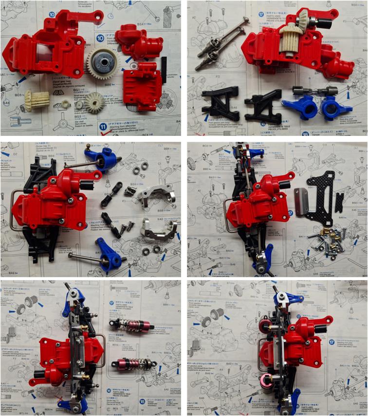
Assemble the front section, which includes the gearbox housing, the suspension system and the steering mechanism. The satellite‑gear differential is replaced with the equivalent and higher‑performance ball differential, item 53070 (left image in the first row). The drive shafts used are the one‑piece universal type, item 53172 (right image in the first row). The C‑hubs are the light‑alloy version, item 53226 (left image in the second row). The shock tower is made of carbon fibre and is part of set 47479 (right image in the second row). The dampers are the low‑friction light‑alloy type, item 53155 (left image in the third row).
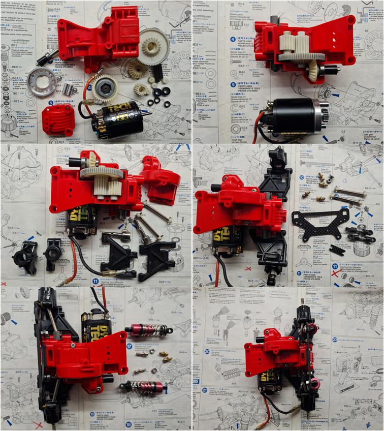
Assemble the rear section, which includes the motor system, gearbox housing and suspension. The satellite‑gear differential is replaced with the equivalent and higher‑performance ball differential, item 53070 and the motor used is the “Dynatech 01R, 19T”, item 53001 (left image in the first row). The circular motor‑mount plate is replaced with the equivalent aluminium version, item 53142 (left image in the first row). The shock tower is made of carbon fibre and is part of set 47479 (right image in the second row). The dampers are the low‑friction light‑alloy type, item 53155 (left image in the third row).
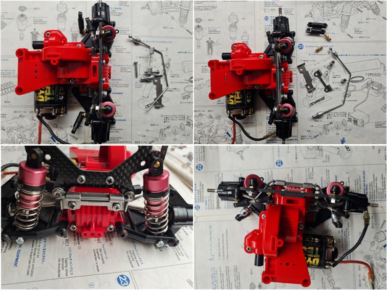
To complete the rear section, install the rear anti‑roll bar, item number 53189 described as “4WD touring and rally car rear stabilizer set for TA02 chassis” (left side of the image).
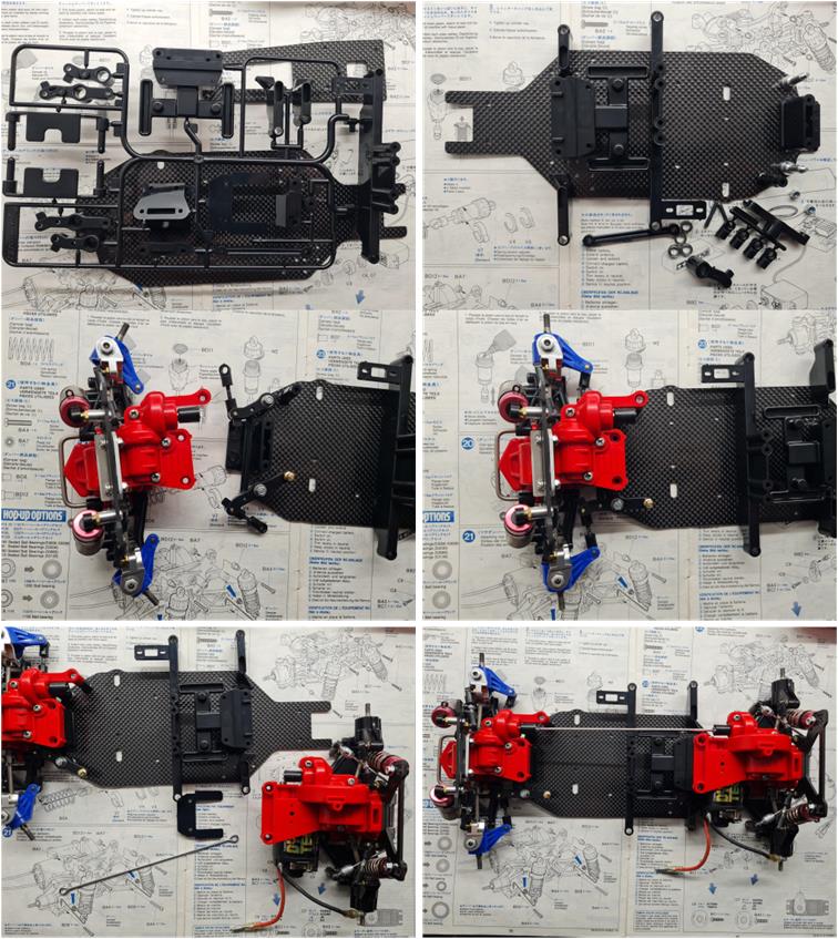
Assemble the central chassis, which is made of two carbon‑fiber plates from set 47479. The two carbon plates are completed with several black plastic components. The front section is the first to be joined to the lower carbon plate (second‑row image), while the rear section is the second to be attached to the lower plate. Pay attention to correctly positioning the driveshaft so that power is transmitted from the rear axle to the front axle (left image in the third row).
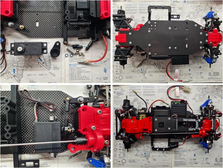
Prepare the Tamiya TSU‑01 servo horn, which completes the C.P.R. 01 two‑in‑one control unit. The servo is fixed to the chassis using the two aluminium mounts, item 53596. After securing the upper plate as well, double‑sided tape can be used to attach the control unit to the chassis (right image in the second row).
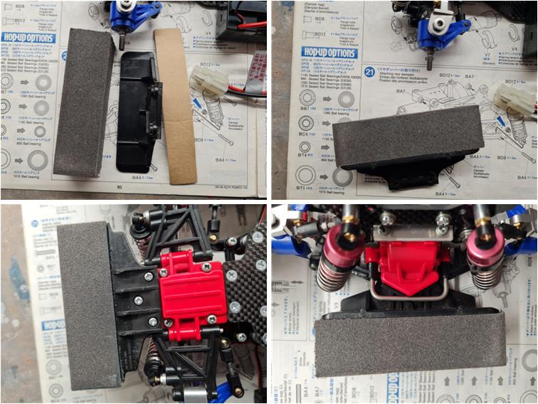
The front bumper is the urethane version, item number 53145 described as “4WD Touring & Rally Car Urethane Bumper”. The bumper is composed of a black hard‑plastic part, a foam insert and double‑sided tape used to join the hard‑plastic part and the foam (left image in the first row). Join the two parts with the adhesive tape (right image in the first row) and then install the complete bumper onto the chassis (second‑row image).
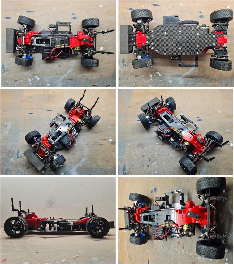
To complete the chassis, install the four body posts used to connect the chassis to the body shell, secure the cables with plastic zip ties, finish the wiring for the motor and the C.P.R. 01 unit and mount the four wheels. Images show the completed chassis.
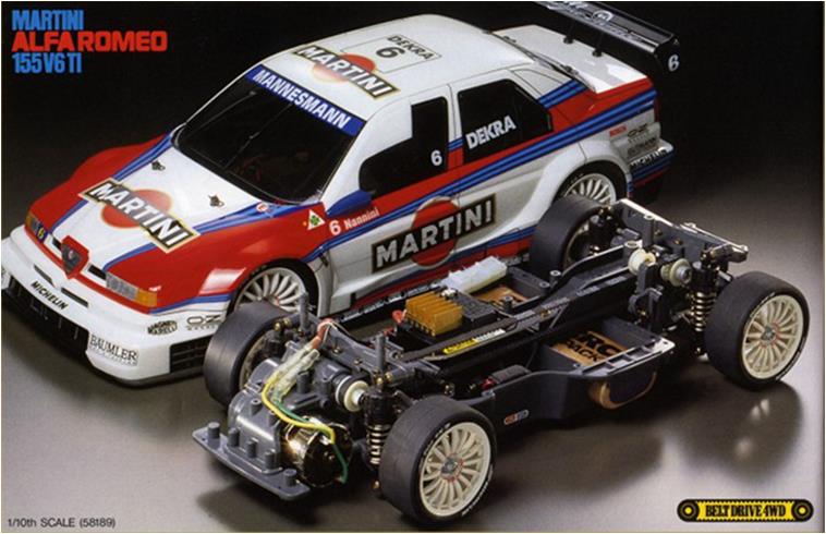
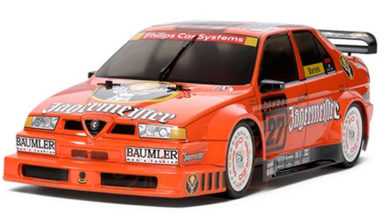
Body restoration There is nothing to restore in the body, just wipe off dust. To date (2024) Tamiya has released these models over the years:
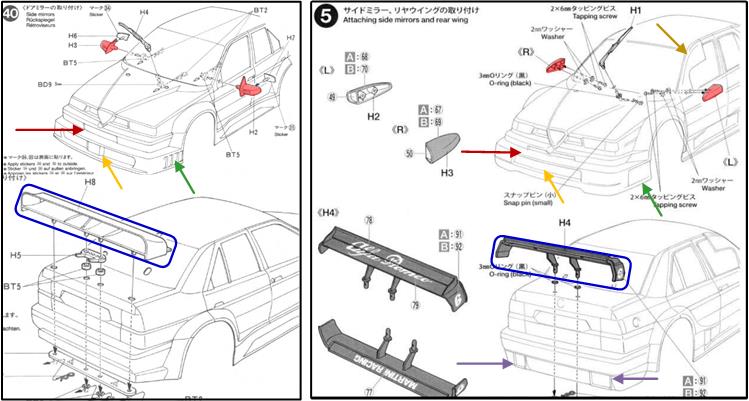
There are two different bodys for the Alfa 155 V6 TI: the first body was used on the red Alfa Romeo and the Jagermeister model and the second body was used on the Alfa Martini and Bosch model. In the image below are excerpts from the body instructions: on the left the first version and on the right the second version. In racing on fast tracks, the biggest problem for Alfa Romeo is poor aerodynamic penetration, which penalises top speed, so Alfa Romeo evolved the body to improve the aerodynamic efficiency of the Alfa 155, which is basically a comfortable middle-class saloon that struggles to compete against coupes like the Opel Calibra that have better aerodynamics and lower ground clearance. The two bodies differ in:
– the shape of the front pillar of the front side windows on the driver’s side and the passenger side (see brown arrow in the second picture on the right). In the second version there is a deflector which has an aerodynamic function to improve the Alfa 155’s penetration coefficient; top speed was one of the points where it lost out to the low Mercedes 190 EVOII and then to the Opel Calibra which was a coupe with better aerodynamics, – the shape of the rear-view mirrors (highlighted in red in both the picture on the right and the picture on the left),
– the shape of the lower air intake on the front bumper (highlighted with an orange arrow both in the picture on the right and in the picture on the left) and the small air intake under the logo on the front (highlighted in dark red both in the picture on the right and in the picture on the left) – the shape of the engine exhausts on the rear bumper which are only present in the second version (double purple arrow on the right in the picture) and – the shape of the rear spoiler (see the two blue boxes in both the image on the right and the image on the left).
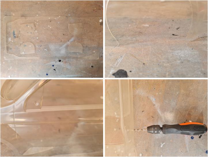
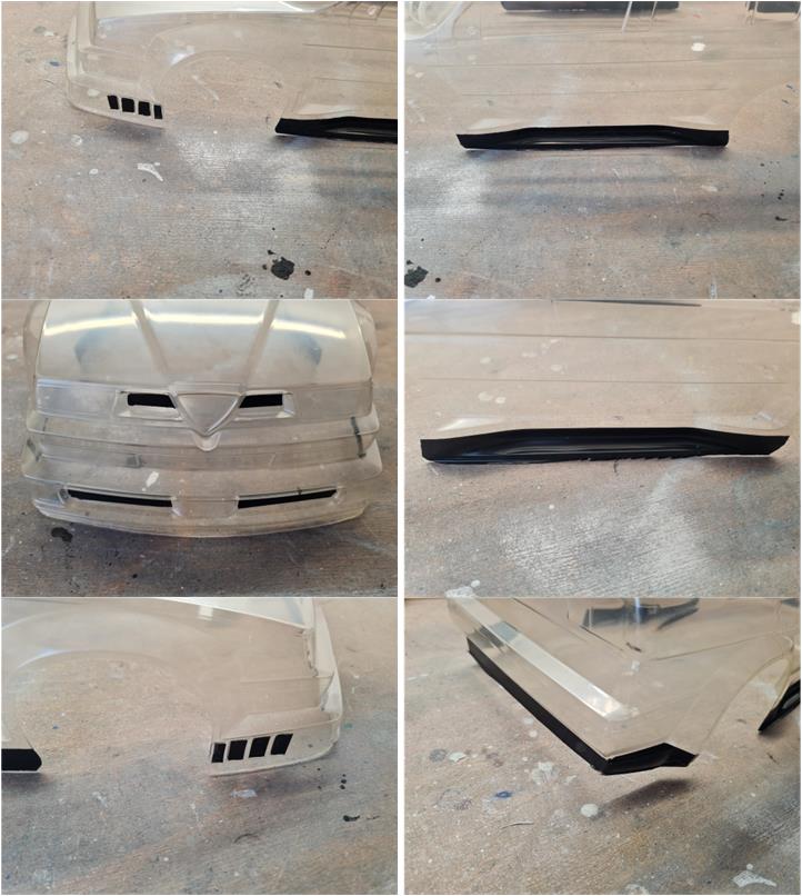
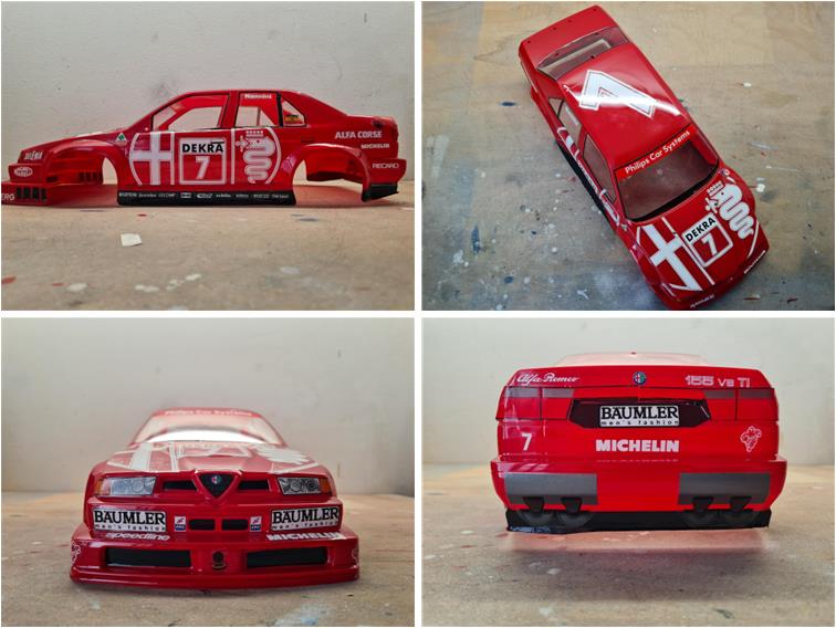
The red Alfa Romeo 155 body shell is new, so the first operation is a complete wash with hot water and dish soap to remove any traces of oil used during manufacturing. The body must be washed and then dried with a kitchen paper towel to remove every drop of water. If droplets evaporate, they can leave limescale marks that would compromise the following painting stages. Cut away the excess material by following the trim lines on the mould. The Alfa Romeo 155 is a standard road sedan with a very tall front section. To improve interior space, the roof sits high above the ground, so very little plastic needs to be removed because almost the entire sheet is used for the body (left image in the first row). Avoid sharp corners; it is better to round every angle with a smooth curve (right image in the first row). Two holes must be drilled to mount the side mirrors using a 4 mm metal drill bit and a hand drill. When drilling, the body may flex; to prevent damage, place a piece of wood inside so that the drill bit pushes the body against the wooden support.
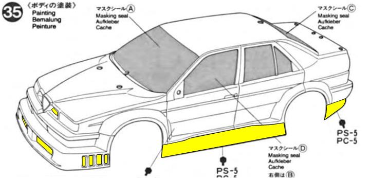
Since this is a Lexan body, the first colour to apply must be the darkest one, which in this case is black. The side skirts under the doors, the front engine air intakes, the wheel‑arch vents and the lower section of the rear bumper are all black. In reality, the side and front air intakes are supplied as black stickers, but based on the experience with the Alfa Romeo 155 Martini, it is better to paint these areas black rather than apply the stickers. The stickers are difficult to position correctly. In the image, the areas to be painted from the inside in black PC5 are highlighted in yellow.
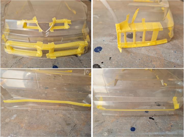
Mask the areas that need to be painted black.
Apply three or more coats of black paint, code PC5, using a brush.
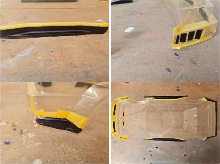
After 24 hours from the last coat of paint, remove the masking and check the final result.
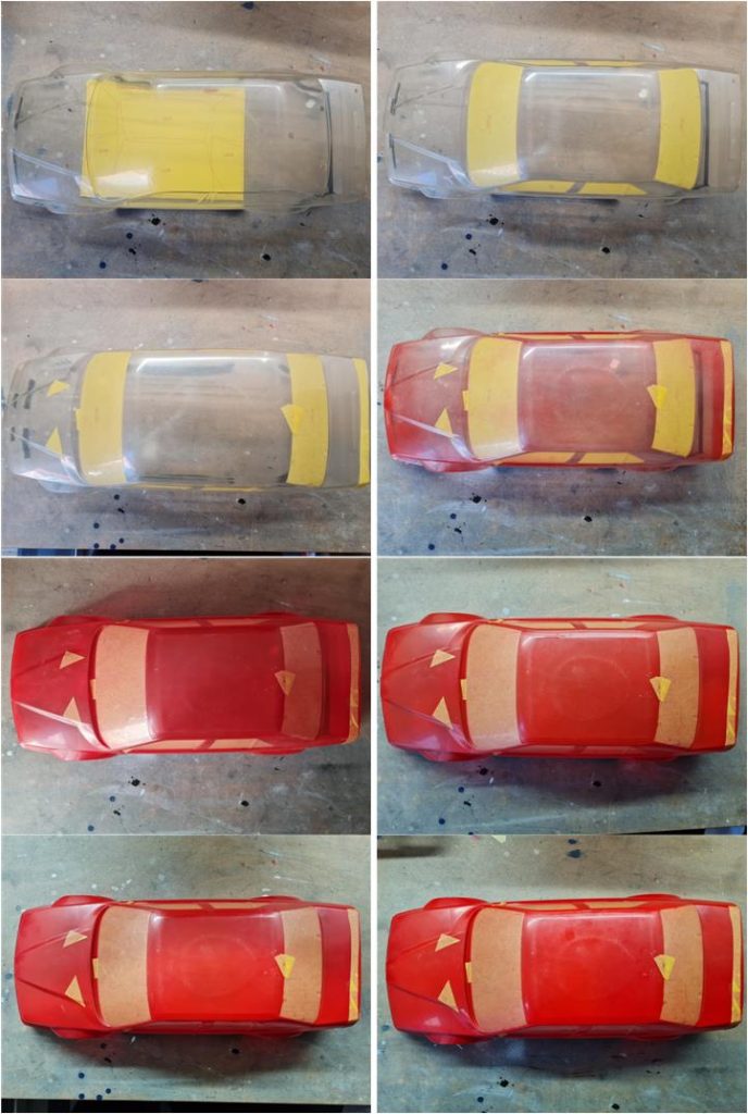
Using the masking included in the sticker set (left image in the first row), cover the six cabin windows (right image in the first row). With the leftover adhesive sheet, seal from the outside the four holes for the body‑mount posts, the two holes for the side mirrors, the hole for the washer nozzle and the four holes for the rear wing (left image in the second row). Apply several coats of red paint, code PS2. The first coat must be very light; this allows the paint to begin adhering to the Lexan and also seals the edges of the masking. If too much paint is applied at once, it will seep between the masking and the Lexan. By applying the first coats lightly, the paint does not penetrate under the masking and helps seal the edges, preventing unwanted colour bleed.
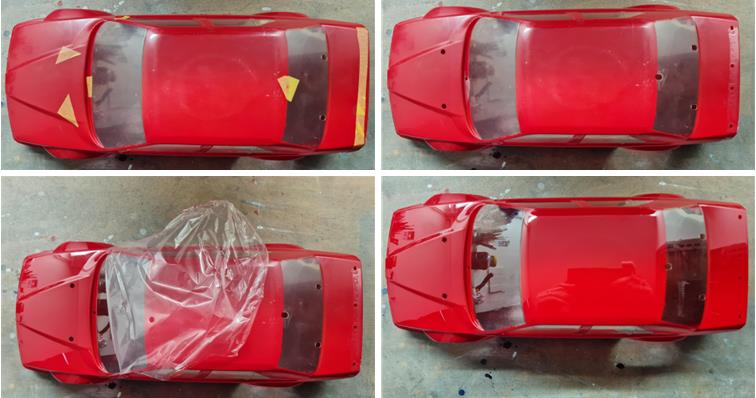
Remove the interior window masking and the external masking (left image in the first row) that covers the holes in the body shell (right image in the first row). Remove the outer transparent protective film (left image in the second row). At this point, the body shell is ready for the decals (right image in the second row).
Remove the interior masking from the cabin windows, as well as the external masking (left image in the first row) that was covering the holes in the body shell (right image in the first row). Then peel off the outer transparent protective film (left image in the second row). At this stage, the body shell is ready for decal application (right image in the second row).
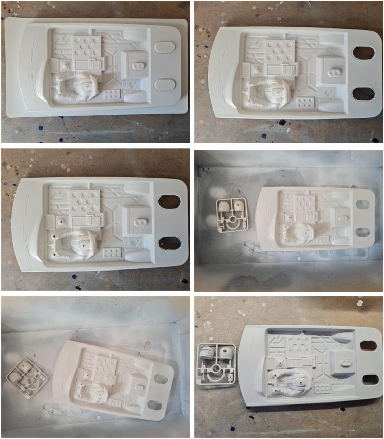
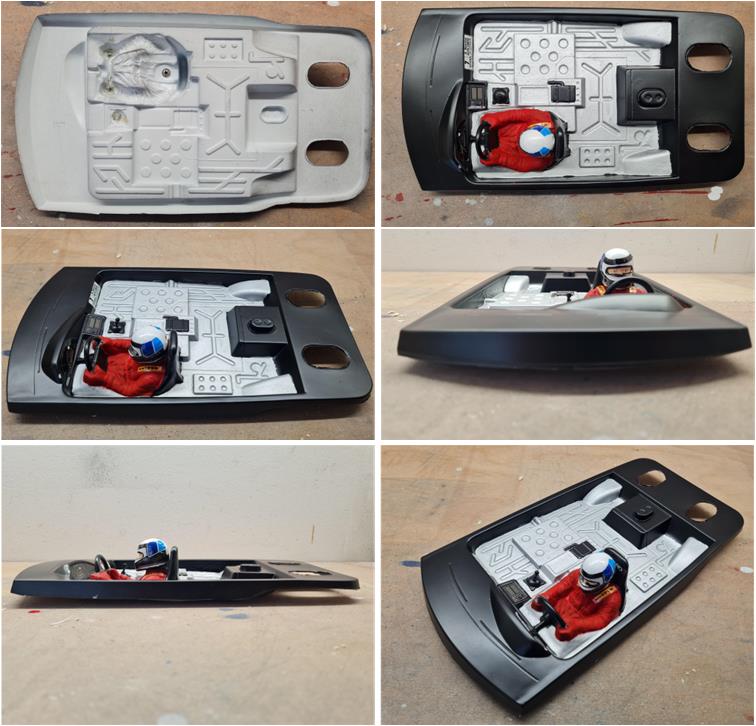
The cockpit Cockpit item number 50457 is the version with only the driver; it is easy to distinguish from the rally version because the rally version also includes the co‑driver. Cut the side edges along the trim line marked on the mould and remove the two rear oval‑shaped sections that allow clearance for the body‑mount posts connecting the chassis to the shell (right image in the first row). To complete the pre‑painting preparation, cut with scissors the cone for the screw that secures the helmet, the two cones for the steering wheel and the cone for the gear lever (left image in the second row). Apply two or more coats of fine grey primer, item 87042, until the surfaces of the cockpit and helmet have turned uniformly grey. The first coats must be very light to avoid forming primer droplets.
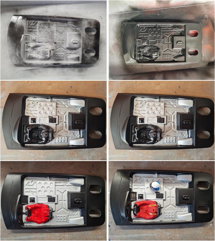
When all surfaces are fully grey, you can apply the matte black TS29 to the cockpit. As with the primer, start with light coats and then gradually increase coverage. No work is done on the underside, which is intentionally left untreated. The final step is to brush‑paint the driver’s suit in red XF7 and the cockpit floor in aluminium grey XF16. These paints must be applied with a brush and at least two coats are needed to achieve proper coverage (right image in the last row). After 24 hours from completing the paintwork, you can apply the decals (left image in the last row).
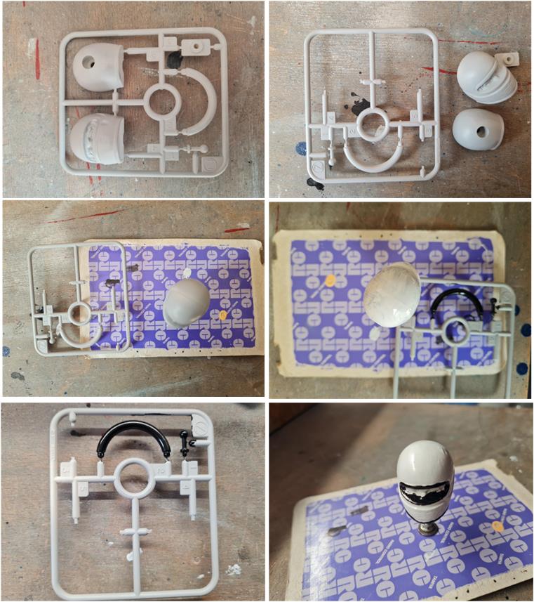
The cockpit also includes the driver with helmet, the gear leve and the steering wheel the driver holds. These three parts come from a single mould (left image in the first row), which also contains the three components needed to assemble the helmet (front shell, rear shell and central plate).
After applying the fine grey primer, you can assemble the helmet and begin applying the first coats of colour:
– XF1 flat black for the steering wheel and some helmet details, – X18 gloss rubber black for the gear lever, – X1 white for the helmet shell.
The steering wheel and gear lever are not removed from the sprue during painting; keeping them attached makes handling easier while applying the colours. Once 24 hours have passed since the paint was applied, you can place the decals on the helmet shell.
The images show the completed cockpit. The steering wheel and gear lever should slot into the cockpit using the holes created by cutting the cones. To secure them to the cockpit, apply a drop of the acetone‑and‑ABS solution. The drop must be applied from the underside of the cockpit (left image in the first row), the side that has not been treated. Acetone attacks paint, so it cannot be applied to painted surfaces. The acetone‑ABS mixture melts the plastics, fusing them together.
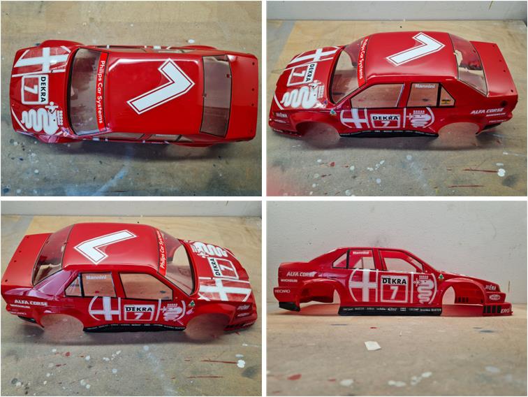
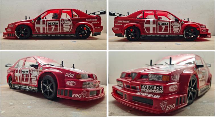
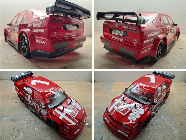
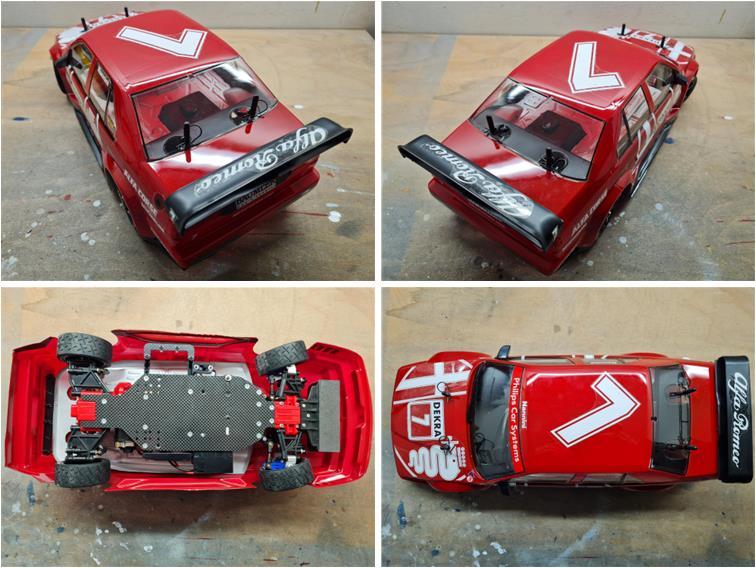
Restored model Images showing the completed model.
Tamiya, original figure, box art, guide book and catalogue are of TAMIYA INC, which does not endose or sponsor www.tamiyaclassic.com. Any brands, logos and trademarks represented on this website are the copyright of their respective owners.