Tamiya F103 LM TRF, article number 58258 offered for sale in 1999 and available on the market until 2000 Body not planned Chassis F103 LM TRF, the abbreviation stands for Tamiya Racing Factory
Analysis of the model to be restored
Today (2024), Ferrari’s great sporting achievement is evident as it returned to compete in the World Endurance Championship (WEC) with the Ferrari 499P, winning the Le Mans 24 Hours in 2023 and 2024:
– in the year 2023, the number 51 car driven by Antonio Giovinazzi, Alessandro Pier Guidi, James Calado wins on debut the first Le Mans faced after returning to the World Endurance Championship and – in the year 2024, the number 50 can driven by Antonio Fuoco, Miguel Molina and Nicklas Nielsen wins the Le Mans 24 Hours race, repeating the previous year’s result.
The Ferrari 499P is equipped with an endothermic drive unit and an electric motor-generator:
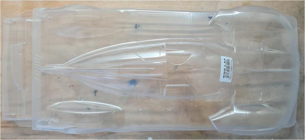
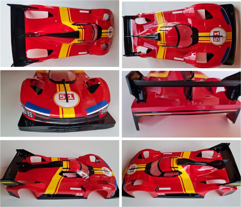
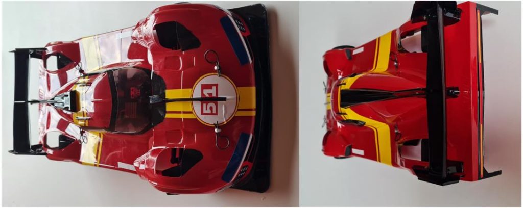
– an endothermic petrol engine with a 120° V6 configuration, displacement 2994 cm3 with turbocharging by two turbochargers for a maximum total power of 680 hp (500 kW) that drives the rear wheels and – an electric motor-generator installed on the front axle with 200 kW (272 hp) that manages a 900 Volt battery pack recharged by the ERS during braking, deceleration and (when possible) by the heat engine. The car is thus equipped with all-wheel drive with total power and weight being managed according to Balance of Performance (BoP). The aerodynamics are a Ferrari style centre project and the carbon-fibre chassis is a Dallara design. Several Lexan bodies have been released on the market that can be installed on 1/10th and 1/12th scale chassis that more or less faithfully reproduce the Ferrari 499P. None of the bodies released today (2024) have been officially recognised by Ferrari. The final choice fell on a Lexan body complete with stickers (see image below).
The rear wing side wings, centre support and rear wing itself as Lexan parts to be assembled separately. The wheelbase of this body is 256 mm and is the same wheelbase as the F103 family, the F103 family comprises several models and different versions. Some models were released on the market in a chassis-only version without body. For such a successful Ferrari model in the endurance racing category, the chassis that best represents it is the F103 LM TRF released only for model number 58258. This model is only available without body and is the highest performance model used by the official Tamiya racing team for track racing. The main reasons for this choice are:
– steering servo installed horizontally lying on the chassis to lower the centre of gravity, – enlarged carbon chassis bottom plate to accommodate the servo and electronics, – rear suspension system – motor housing evolved with respect to that of the standard F103 chassis; the system is articulated with respect to the T-plate – front suspension system evolved from that of the standard F103 chassis with upper suspension arms articulated in relation to the chassis and – 19 Hop Up provided as standard compared to the standard model from which it was developed. The starting model is the F103 LM chassis installed on the Audi R8R code number 58247, the modifications made are all aimed at increasing the overall performance of the model.
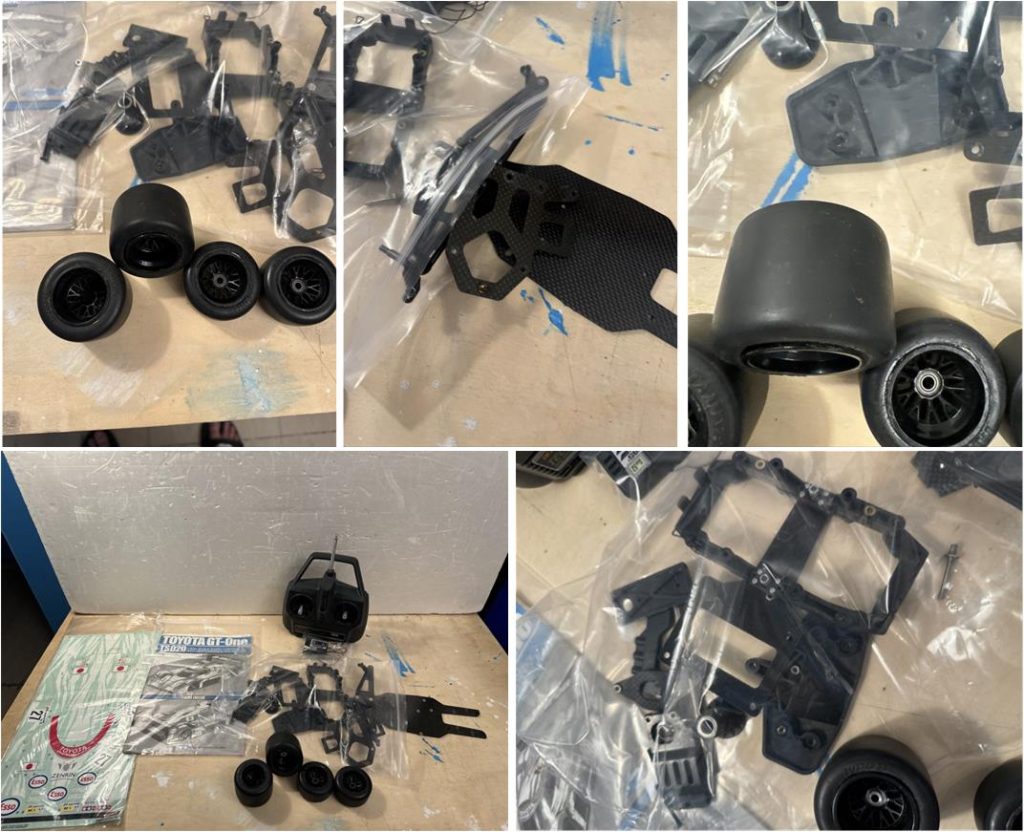
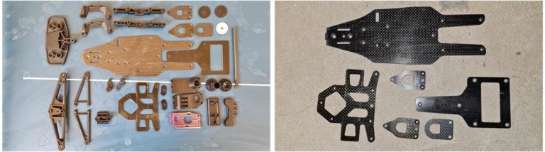
The purchase fell on this batch of parts shown in the image below.
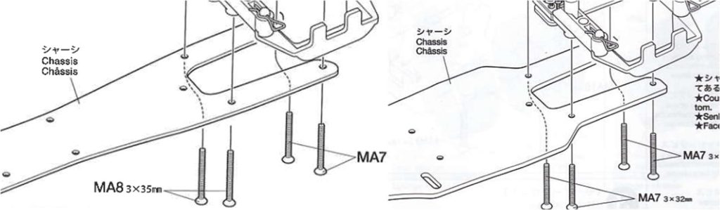
Analysis of the lot reveals that: – there are the stickers and the assembly instructions manual for the Toyota GT-ONE TS020 model that is factory fitted with the F103 RS chassis; the body of the Toyota GT-ONE is missing, – it is evident that there are several parts in the lot that are not assembled together and that the chassis of the Toyota GT-ONE is the F103 RS which differs greatly from the F103 LM TRF chassis. From the pictures above it can be seen that there are several inconsistencies between the components of an F103 RS chassis and the parts in the lot. The inconsistencies confirm that the batch is composed of parts taken from different models; the chassis appears to be an F103 LM TRF and not the F103RS chassis of the Toyota GT-ONE. The first obvious difference between the F103RS chassis and the parts that are present in the batch is the lower fibre plate; in the F103 RS chassis the lower plate is the one in the narrow version (image on the left below) while in the images above it is evident the fibre plate in the wide version (image on the right below) that allows the steering servo to be installed lying down, this system is typical of the F103 LM TRF model.
The second obvious difference between the F103 RS chassis and the parts on the lot is the front suspension system; on the F103 RS chassis the front suspension is fixed upper and lower arms (image left below) while in the images above the front suspension system with fixed lower arms and articulated upper arms is evident (image right below), this system is typical of the F103 LM TRF model. The articulated upper suspension arm installed on the F103 LM TRF chassis is an evolution of that on the F103 RS chassis,
The third obvious difference between the F103RS chassis and the parts on the lot is the central frame that houses the single shock system and acts as a battery holder; in the F103 RS chassis and most models equipped with the F103 chassis, this structure is rigidly attached (image left below) to the T-plate while in the images above this structure is articulated (image right below) in relation to the T-frame; this system is typical of the F103 LM TRF model. The articulated frame installed on the F103 LM TRF chassis is an evolution of that of the F103RS chassis.
These three differences between the F103 RS chassis and the parts in the lot make it clear that what can be assembled is the F103 LM TRF chassis with stickers and Toyota GT-ONE manual. The F103 LM TRF chassis exists only without body, there are several possibilities why there are parts from different models in this lot:
– it is probable that a chassis model 58258 was bought to join it to the Toyota GT-One body part number 50824, – it is likely that the previous owner wanted to increase the performance of model 58229 (Toyota GT-ONE with F103 RS chassis) by incorporating the improvements introduced with model 58258 or – it is likely to be a batch composed of parts from models 58258 and 58229 (Toyota GT-ONE with F103 RS chassis).
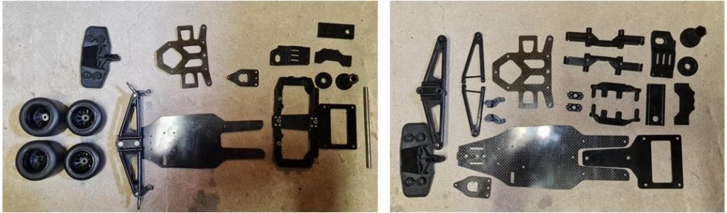
Any theory has its own possible kernel of truth and it is possible to find countless others to add to the three listed above. The above analysis based only on the pictures in the advertisement is confirmed upon arrival of the package; the left picture shows the newly arrived parts and the right picture shows the fully disassembled model.
These three differences between the F103 RS chassis and the parts in the lot make it clear that what can be assembled is the F103 LM TRF chassis with stickers and Toyota GT-ONE manual. The F103 LM TRF chassis exists only without body, there are several possibilities why there are parts from different models in this lot:
– it is probable that a chassis model 58258 was bought to join it to the Toyota GT-One body part number 50824, – it is likely that the previous owner wanted to increase the performance of model 58229 (Toyota GT-ONE with F103 RS chassis) by incorporating the improvements introduced with model 58258 or – it is likely to be a batch composed of parts from models 58258 and 58229 (Toyota GT-ONE with F103 RS chassis).
Any theory has its own possible kernel of truth and it is possible to find countless others to add to the three listed above. The above analysis based only on the pictures in the advertisement is confirmed upon arrival of the package; the left picture shows the newly arrived parts and the right picture shows the fully disassembled model.
Chassis restoration
The chassis has already been dismantled in its entirety when the model arrives, so it is possible to move on to the cleaning operation. Sequence of operations for the restoration of the larger plastic and fibre parts:
– wash surfaces with kitchen soap using a medium or hard bristle brush to reach the most hidden spots, – polish surfaces with toothpaste or polish, – for carbon parts only, treat the parts with black shoe polish
Left image are the parts before treatment and right image are the fibre parts after treatment
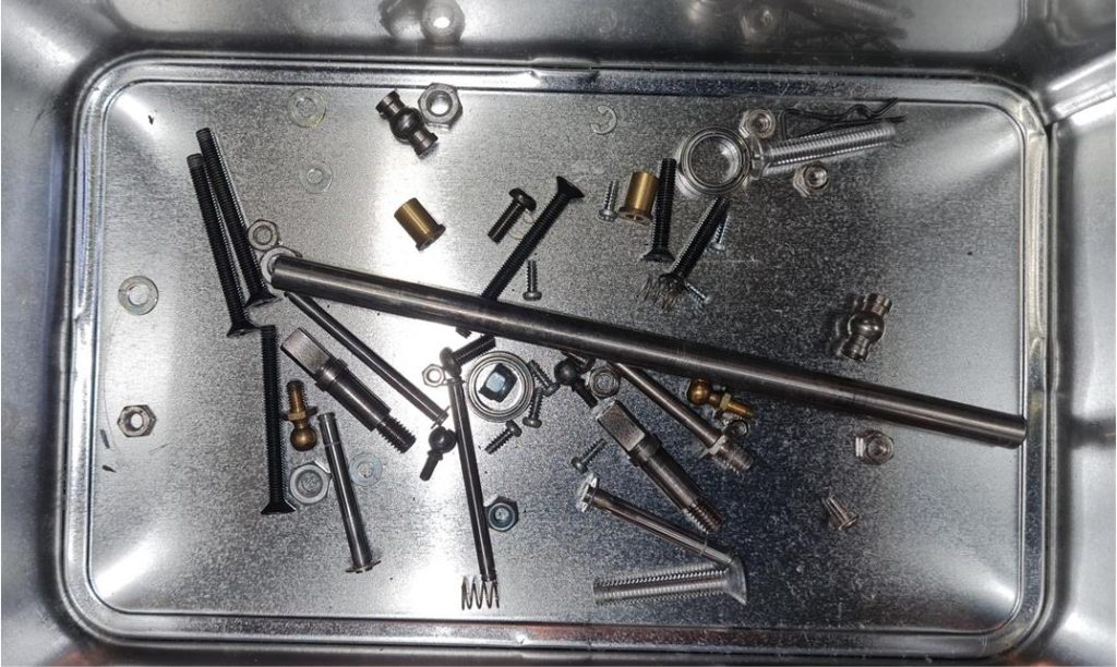
The metal parts were immersed for six to seven days in diesel oil (image below); the diesel oil has the property of degreasing the parts, removing rust and oxidation. After treatment, metal parts remain shiny and covered with a thin film of oil that preserves them from oxidation for a long time. If the metal parts are not too oxidised or dirty, the diesel treatment is more effective than the ultrasonic washing machine.
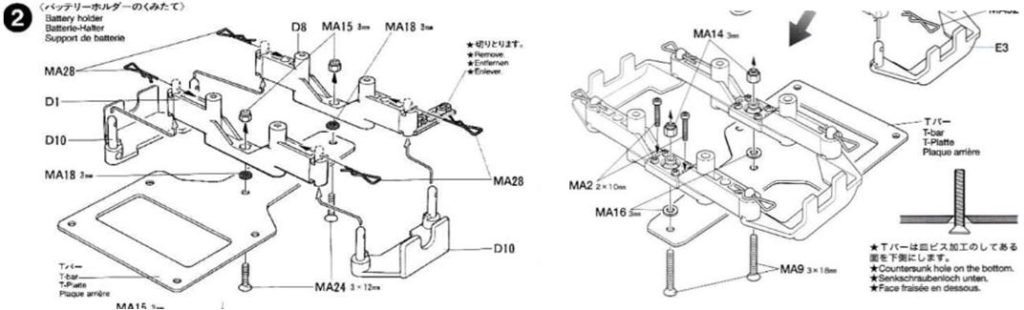
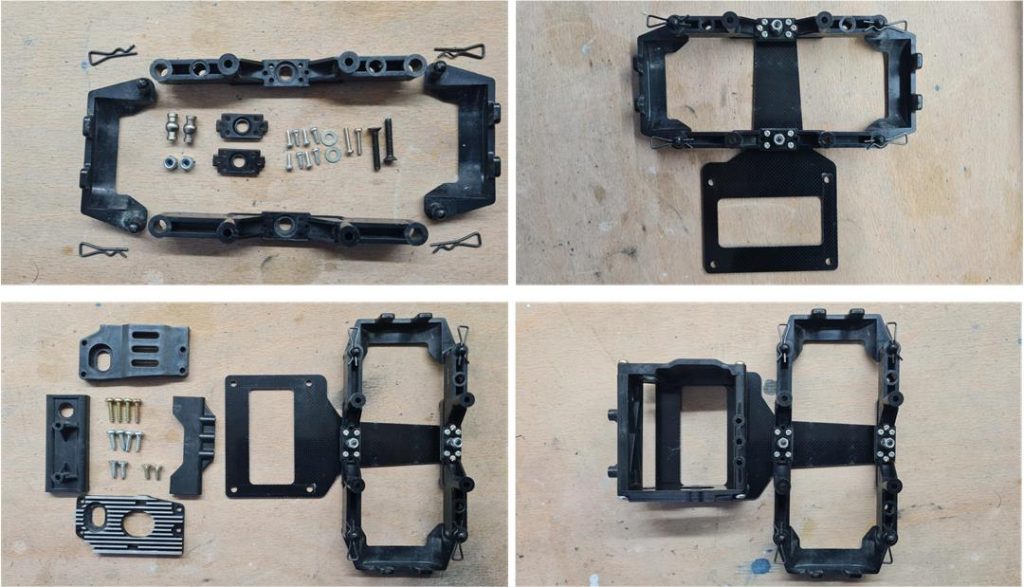
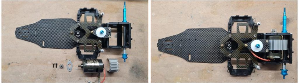
At this point all parts are ready to be assembled. Follow the sequence of pictures summarising the steps in assembling the model. The assembly phase starts with the rear structure installed on the T-fibre plate complete with the section to house the battery. The rear system housing the electric motor and rear axle was restored to factory condition by adding the black anodised aluminium plate for electric motor installation. The pictures in the left column show the parts before installation and the pictures in the right column show the assembled parts.
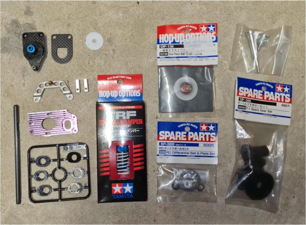
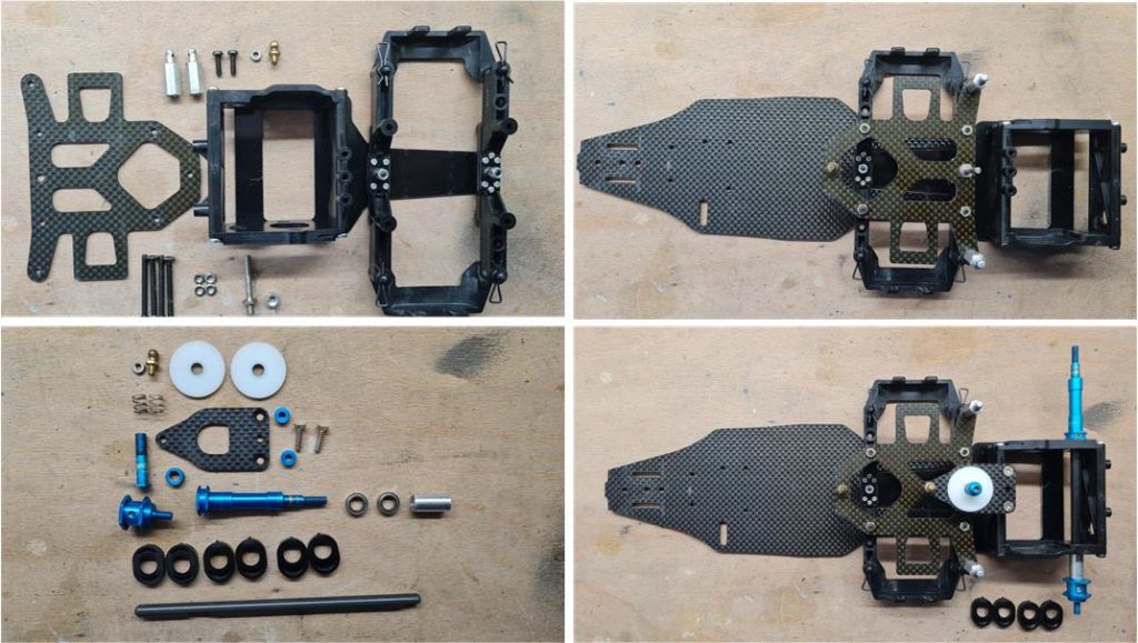
Assemble the rear end with the complete fibre top plate of the single shock system. The axle provided by the factory is aluminium, the titanium axle (part number 53396) saves more than half the weight with the same efficiency. Anyone intending to use the model on the track performs this modification and it is obviously a performance-enhancing part. Complete installation of the white Teflon discs of the rear single shock system. The aluminium joints are the light blue anodised ones. The pictures in the left column show the parts before installation and the pictures in the right column show the assembled parts.
Install the electric ‘Sport Tuned Motor’ part number 53068 complete with cooling fin system, this is an aftermarket accessory to improve performance. The picture on the left shows the parts before installation and the picture on the right shows the assembled parts.
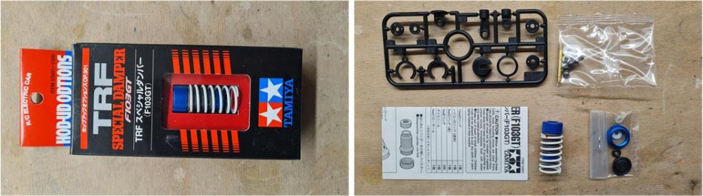
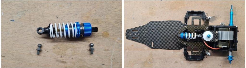
Rear shock absorber is the special TRF model for the high-performance F103GT chassis part number 53901. The package includes blue anodised aluminium body and rings, plastic parts, white spring and instruction manual.
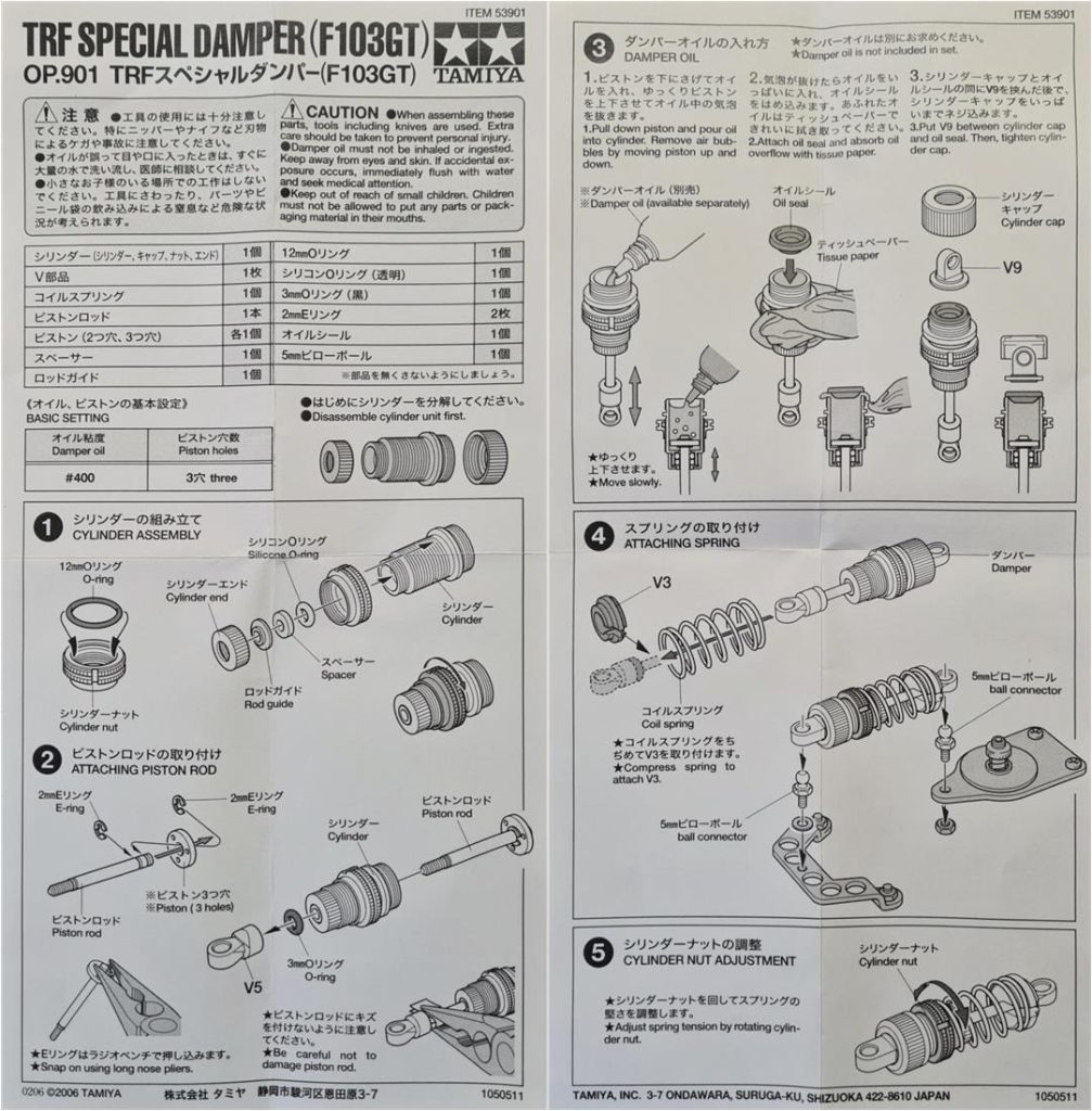
The instructions for building the shock absorber are complete and clear and the steps are relatively few.
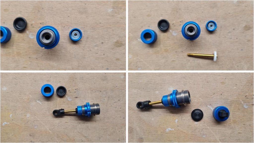
The first operation is to install the black rubber O-ring inside the aluminium ring nut, which is screwed onto the aluminium central body. The function of the ring nut is to adjust the compression of the white spring. Prepare the plunger by joining the metal pin with the white Teflon perforated disc with two holes to pass oil through. Install the plunger inside the central body and screw in the plastic pin securing the ball joint. You can now fill the central body with oil and close the shock absorber.
Having completed the construction of the shock absorber, proceed with installation on the frame, the two aluminium ball joints are included in the package code number 53901.
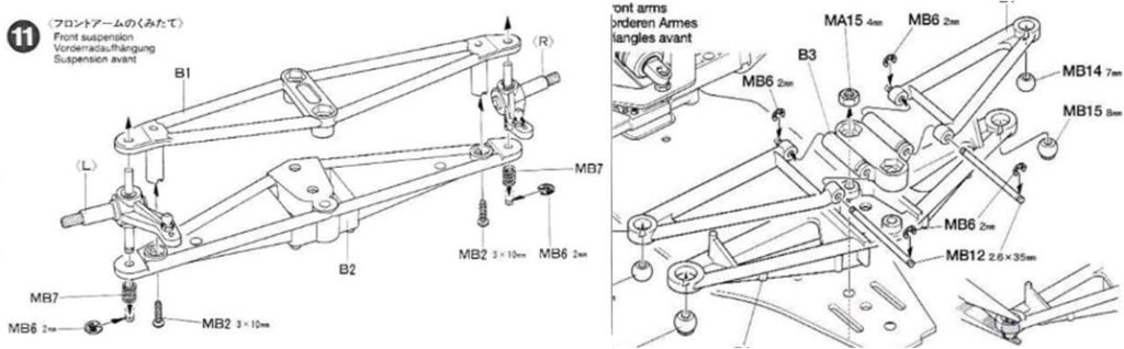
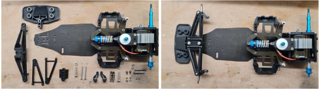
Now it is time to move on to the front suspension complete with shock absorbers and steering system. The hard plastic front bumper that characterises the F103LM chassis is damaged and marked by debris encountered on the track, but it can still be used. The suspension of the F103 LM TRF model has articulated upper arms, which is an evolution of the basic F103 chassis model. The picture on the left shows the parts before installation and the picture on the right shows the assembled parts.
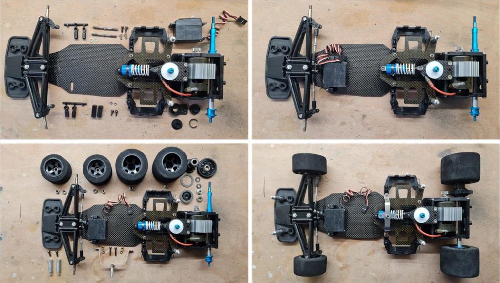
The time has now come to install the steering system: the arms are double-screw adjustable and the servo is installed horizontally lying on the chassis. This system provides better control of the toe-in of the front wheels, better steering angle adjustment and better weight distribution. The four wheels are made of sponge with a black rim. To complete the chassis, install the four towers that secure the body to the chassis and metal antenna holder arch. The pictures in the left column show the parts before installation and the pictures in the right column show the assembled parts.
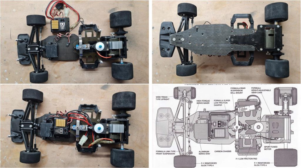
Having installed the receiver integrated with the electronic speed controller for the electric motor, the chassis is now ready to receive the body in marriage. For electronics, we chose a control unit from Tamiya code CRP P160F consisting of a steering servo and receiver unit with integrated electric motor speed controller. The electronics are suggested in the instruction manual (see image on the right of the second line). In the image on the right of the first line you can see the scratches on the front bumper and the lower fibre plate that have not been completely restored, the treatment carried out has removed many imperfections; the deeper ones have not been completely eliminated
Body construction
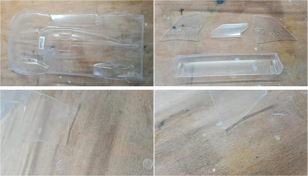
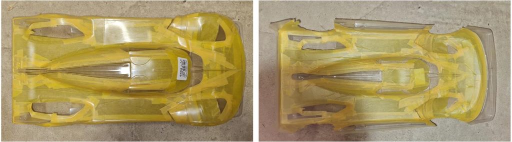
The first thing to do with any Lexan body is to cut off the excess parts: Lexan bodies are made by hot forming a sheet of Lexan, this process leaves a lot of excess parts. First, cut off the excess body parts (top left image), cut out the parts of the rear wing complex (top right image) and cut out the wheel arches. For this operation it is best to use a curved-tipped scissor used for cutting gauze and then process the body with 400-600 grit sandpaper. At this stage great care must be taken not to accidentally work on the inner surface of the body, which would be damaged. Using the abrasive paper gives continuity to the cut and removes all sharp corners that are possible sources of tears in the body in the event of impacts (see blunt corner of the rear wheel arch in the picture below right).
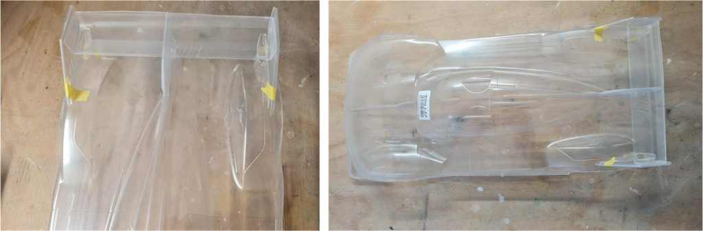
Check that the joint lines between the body and the rear wing assembly have been cut correctly. Use masking tape to secure the side wings, centre support and rear wing to the body. Once you have checked that the parts fit perfectly, move on to machining the openings above the wheels.
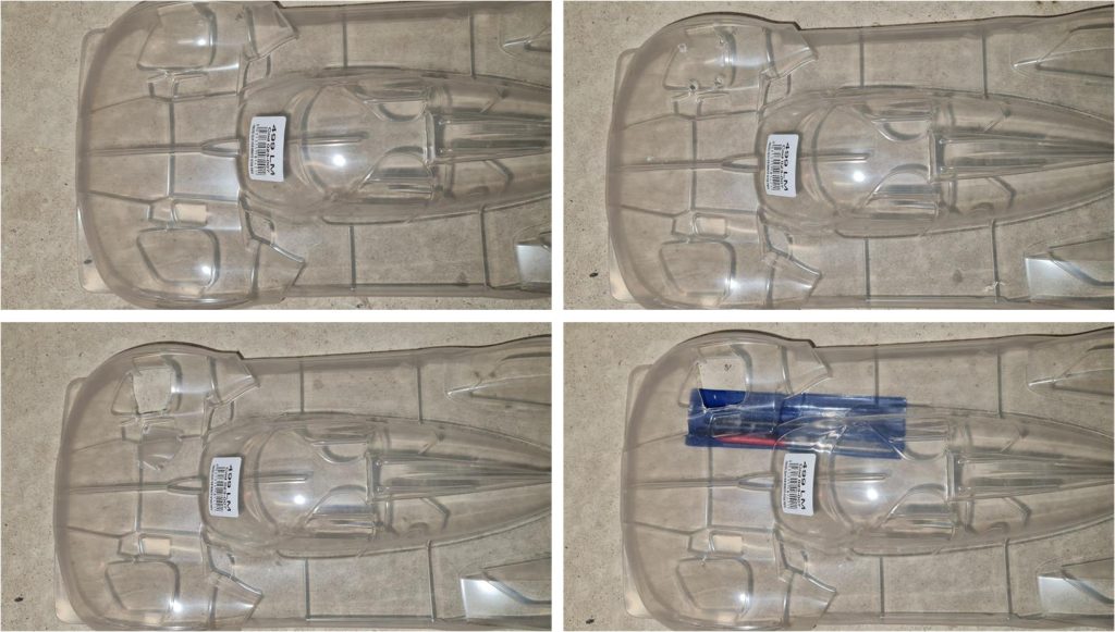
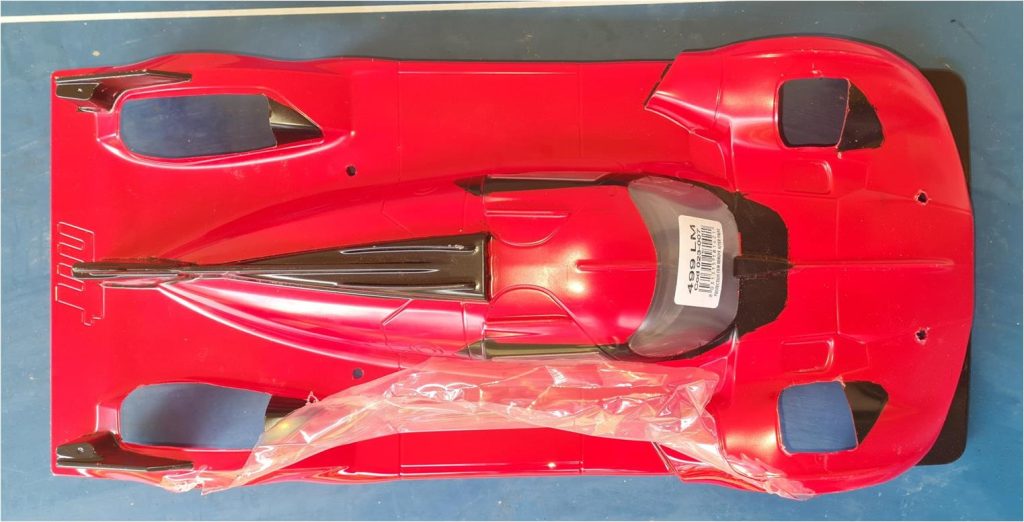
At the four wheels, the body of the cars involved in endurance racing have four openings that prevent the cars’ bodies from becoming wings. These four openings prevent the body from generating lift and the car from taking off down the straight as has happened in the past with some cars, for example Mark Weber’s Mercedes CLR at Le Mans in 1999. The carambole in question was generated by a combination of factors such as aerodynamics, depressions in the road surface and high speed; but since then much attention has been paid to this aspect by placing limits on body shapes. These four openings allow a glimpse of the suspension and mechanical parts, so rather than paint the openings black, it is better to cut out the body, an effect that makes the model more realistic. To construct these four openings in the Lexan body, follow this sequence of operations – drill four holes with a 4 mm drill bit at the corners of the opening (image top right), the opening is marked out in the body by the demarcation lines; to prevent the Lexan from breaking under the pressure of the drill bit, place a piece of wood against it so that the piece of wood acts as a base for the Lexan body and the latter cannot flex, – using scissors, cut the Lexan by joining the four holes to create an opening (picture below left). The opening must be smaller than the desired size, – finish the edges of the irregular opening cut out in this way with an iron file and sandpaper and – repeat the same operation for the other three openings
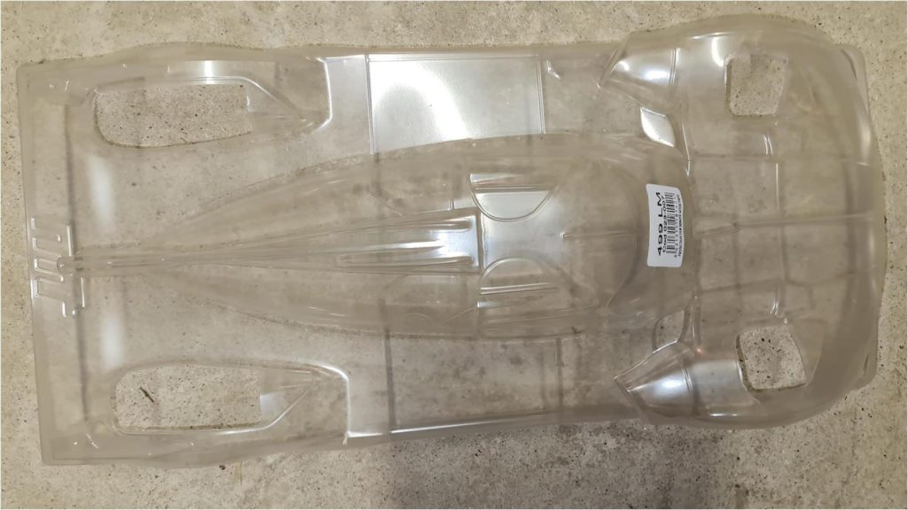
The body looks like this after the four openings have been made
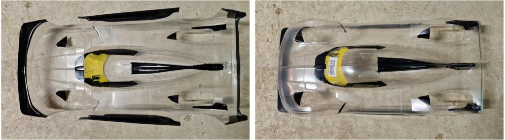
When colouring transparent Lexan bodies, colours should be applied from darkest to least dark. Mask the inside of the body in order to apply black.
After applying the black, remove the main masking and leave the masking of the passenger compartment windows.
Apply red paint to the body and then remove the masking from the cockpit windows. After this step, the protective film covering the top can be removed.
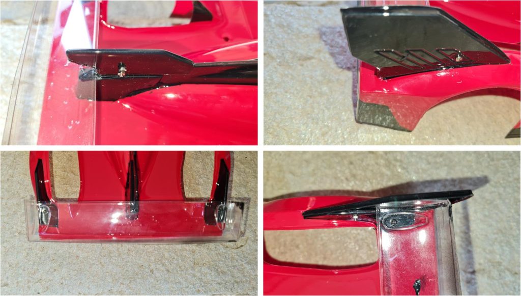
Colour the right side wing (see image on the right in the first row), left side wing and centre wing (see image on the left in the first row) black. Attach these parts to the chassis using 2 mm diameter nuts and bolts. The two side wings and the centre wing support the rear spoiler (picture on the left in the second row), try installation and then attach the spoiler to the body using 2 mm nuts and bolts (picture on the right in the second row). Colour spoiler black.
The stickers that complete the body are of good quality, but sometimes they are absent or do not integrate well with the paintwork done. The manufacturer of the Lexan body expects the black parts and the four openings at the wheels to be black stickers. In the process we have just performed, we preferred to colour the black parts and cut out the four openings, so the parts do not always fit perfectly with the stickers. For these reasons, some stickers were cut from coloured vinyl sticker sheets:
– from a yellow vinyl sheet cut out the side and front strips, – from a white vinyl sheet cut out the stripes at the side of the cockpit, the stripes under the number 51 applied to the two sides at the cockpit and the two front stripes, – cut out the two front rectangles from a blue vinyl sheet.
The bodywork is now ready to be married to the chassis.
Restored model
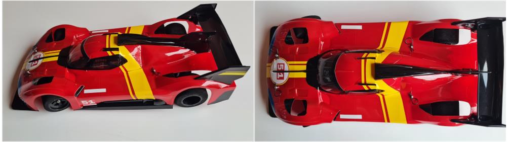
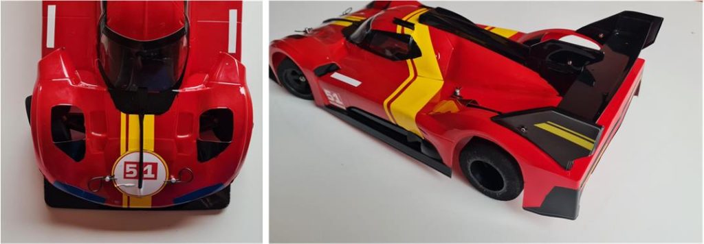
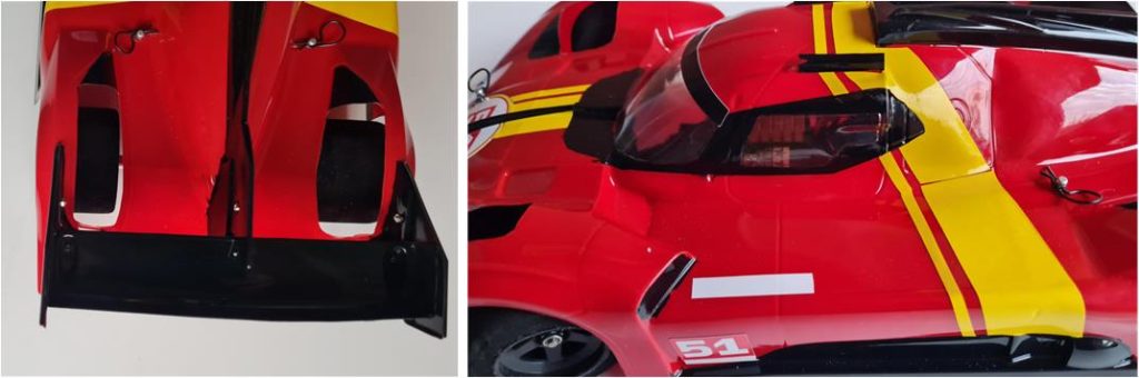
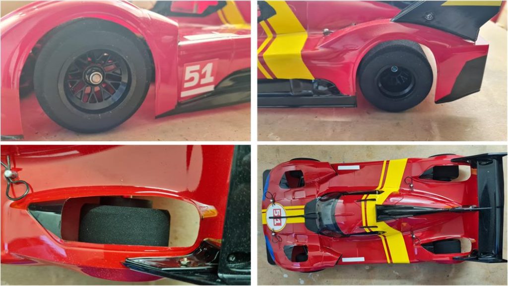
Pictures showing the finished model. Especially at the front, the two openings at the wheels show the suspension arms as on the car that raced at Le Mans.
Updates
Some modifications have been made to improve the performance of the project:
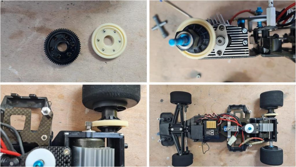
– the rear main gear was changed by inserting the 93-tooth gear from the spur gear set 93T and 104T racing developed number 53104. This gear is the one provided by the factory. In the picture to the left of the first row, the 93-tooth gear is the white one,
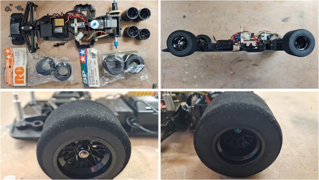
– the rims were changed by inserting new ones with thin spokes (see picture on the left in the first row) that are closest to those on the real model – four new sponge wheels were installed; front wheels code number 50441 and rear wheels code number 50390
The end result does not change much, but is closer to the real model.
Tamiya, original figure, box art, guide book and catalogue are of TAMIYA INC, which does not endose or sponsor www.tamiyaclassic.com. Any brands, logos and trademarks represented on this website are the copyright of their respective owners.