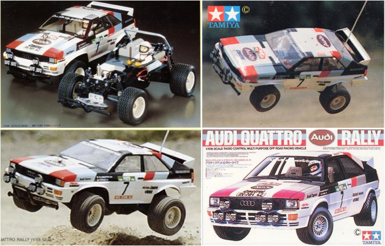
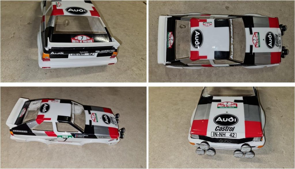
Model Tamiya Audi Quattro, model number 58036, offered for sale in 1983 and available on the market until 1985 Lexan body with styrene parts Quattro chassis
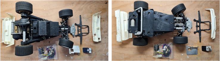
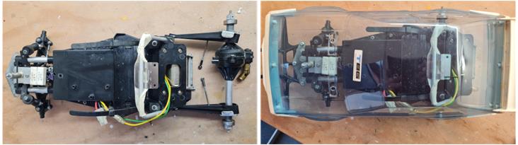
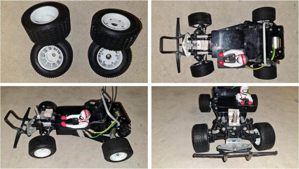
Analysis of the model to be restored After a first analysis, this restoration does not present any particular problems because there are no broken parts; at most there are missing parts to be found later. It is definitely a model that has been used, but from the photos in the online ad, it does not seem to be in such bad shape. Starting from the front going towards the rear, the analysis reveals that:
– the plastic bumper and its L-shaped metal plate are present; the bumper shows several signs of wear and impact, – the electronics box appears to be intact; the lower part shows signs of wear, – the aluminium roll bar is present and intact, – the four wheels with rims are present; the tread is not worn. These tyres were used on a few models (Audi Quattro Rally model number 58036, Lancia Rally model number 58040 and Opel Ascona model number 58037) and are very rare, – the metal plate for the steering servo and the mechanical speed control servo is present, – the resistor holder for the mechanical speed control is present; this model has two resistors, – the front steering has completely incorrect toe-in; despite this the wheels are not worn unevenly so the model has travelled little in this configuration – the rear gearbox part complete with electric motor appears complete and undamaged at first glance,
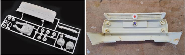
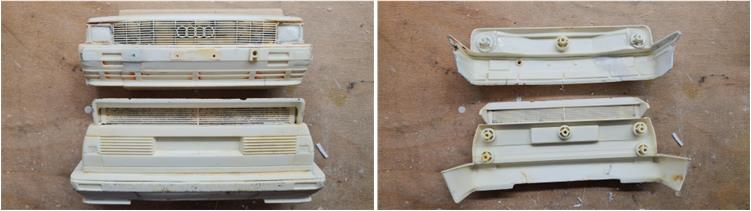
The Lexan body is absent; ‘only’ the front and rear bumpers are present. In fact, these two parts have been used a lot and bear the signs of time; they are very rare to find. Starting from the front going towards the rear, the analysis reveals that
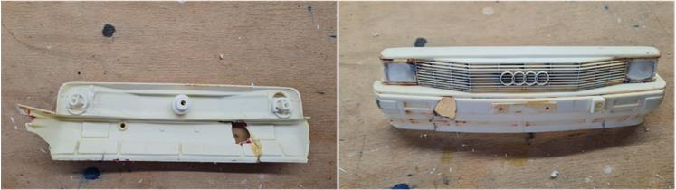
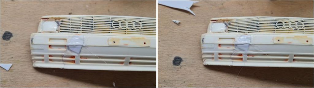
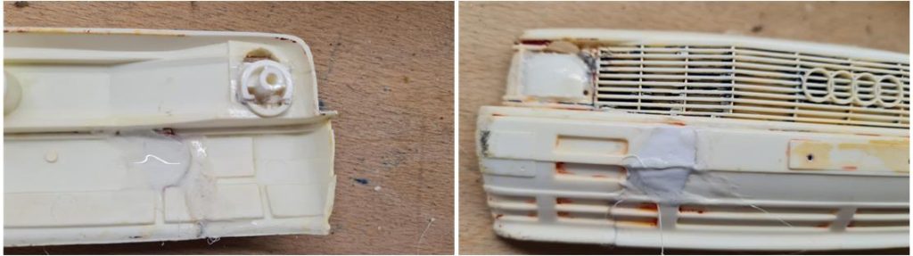
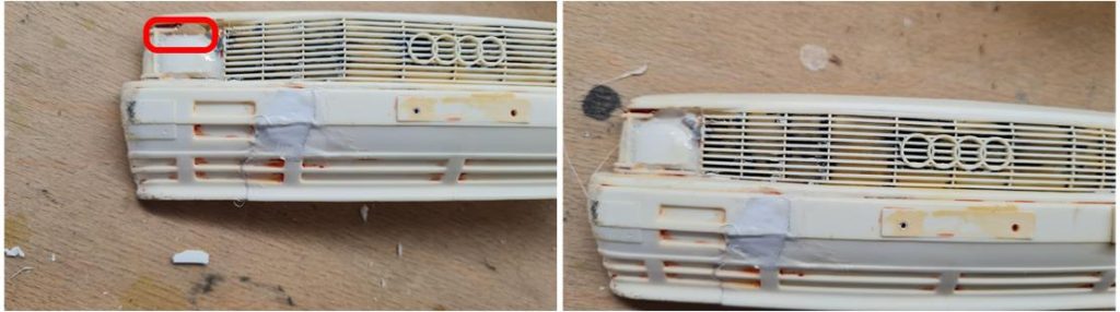
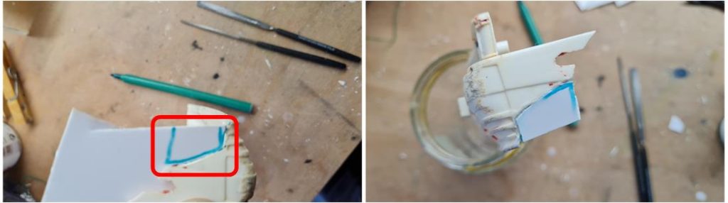
– the right side part of the bumper with front radiator grille is missing, – there are holes at the height of the two front headlights on both the right and left side of the bumper with front radiator grille. At the height of the headlights on the inside, there are towers to secure the bumper to the body, which must therefore be rebuilt, – there is a hole in the lower right front part of the bumper with front radiator grille that is almost certainly the result of an impact, – the rear looks better with only cracks,
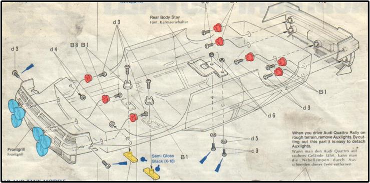
– the three + three front lights are missing (highlighted in blue in the picture), – the top-hat shaped blocks that fit inside the body to attach the two bumpers to the body are missing (highlighted in red in the image) – the two bonnet grilles are missing (highlighted in orange in the image),
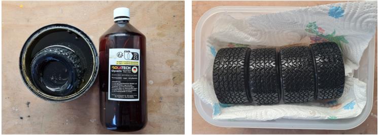
Chassis restoration Separate the tyres from the rims to proceed with regeneration: this operation takes between 20 and 25 days. It should be started first to avoid delaying the restoration. Prepare the tyres by washing them with hot water and detergent kitchen soap that removes all dirt, grease and dust. Soak the rubbers in glycerine for about ten days. During this phase, the glycerine fills the gaps left by the rubber particles and restores elasticity and shine to the rubber.
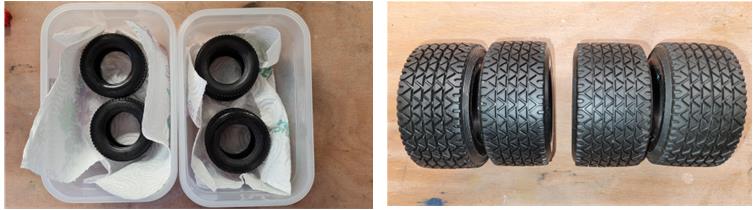
After this treatment, let the gum rest and wait a week for the gum to emulsify all the excess glycerine absorbed. The gum should be left in a container and the paper towel on which it is placed should be replaced every day. When the gum stops emulsifying glycerine, it should be left for a further seven days, cleaning the surface of the gum every day with kitchen paper (left in the picture), at which stage the last excess glycerine absorbed by the gum is removed and the gum becomes shiny and elastic again. At least three weeks are needed to complete the work (right in the picture).
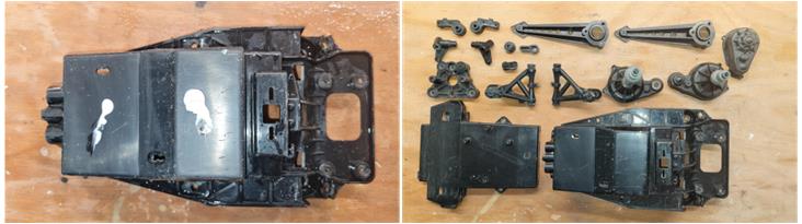
Disassemble the frame to check every part; at this stage look for broken parts, missing parts, modified parts, screws that do not unscrew…
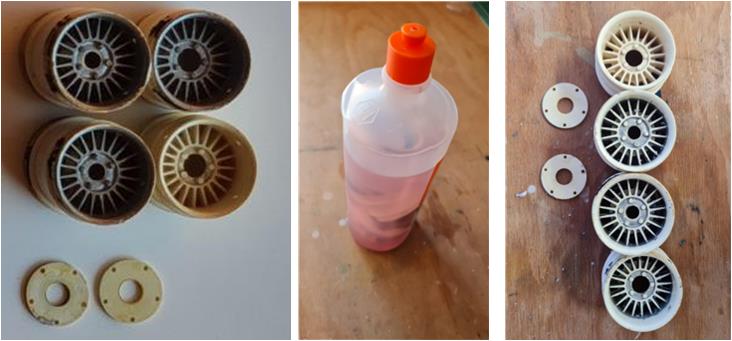
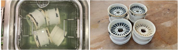
– the rims have been silver-coloured, in carrying out this operation the previous owner did not apply any primer so the paint has lost its grip over time. Remove the wheels from the car and separate the bearings from the front wheels; soak the rims in 90% pure isopropyl alcohol. Without damaging the plastics, it is possible to treat it with up to 99% pure alcohol; take care to handle alcohol carefully, protecting eyes and hands from direct contact. Alcohol chemically attacks the paint, which dissolves. After 24 hours, the rims should be wiped with a paper towel immediately after removing the rims from the alcohol bath, to prevent alcohol evaporating and the paint from turning solid again. Even if one of the four rims was paint-free, it also undergoes this treatment for a general degreasing of the surfaces. The picture on the right shows the rims after only one day of treatment, repeat the operation two or three more times. At the end of the process, the rims are ready to receive the primer and glossy white TS26 paint.
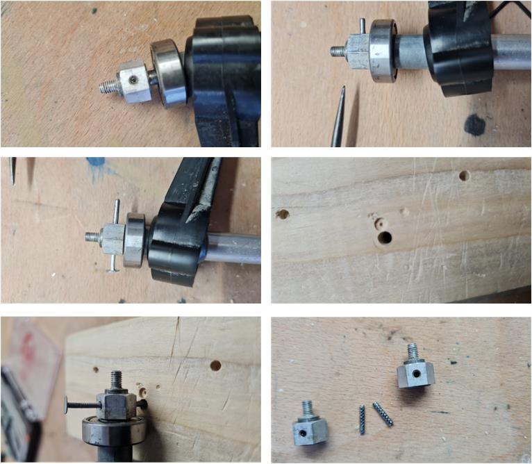
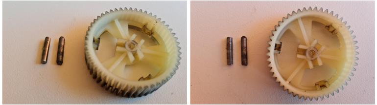
– disassemble front axle with its spring suspension comprising the steering system, – disassemble rear axle with its spring suspension comprising the transmission – disassembling the rear hubs is not straightforward as it is necessary to extract the pin that holds the hub together with the axle. Picture sequence showing how to extract the pin: use an awl so that you can push the pin out of the hub; image number 2, use a very small hammer to gently tap the awl so as not to damage the mechanical parts, insert a nail of the correct diameter when the pin comes out just enough to make the operation possible; image number 3 prepare a 4 mm diameter hole on a wooden board; image number 4, position the hub in such a way that when the nail pushes the pin out it can fall into the hole just made; image number 5 push the nail in such a way that the pin is pulled out of the hub, pull the pin out of the hole in the piece of wood, The two pins are original so over time no one has lost them or replaced them with similar ones, the pins have the two knurled edges that join together like two rows of teeth; image number 6.
Once all the parts have been disassembled, they can be analysed to look for any anomalies: the pin of the main differential gear is not original, it has been badly cut with a bolt cutter from a round steel bar of the right diameter. The shearing operation is not a clean cut; a shearing leaves the surfaces of the two bases not flat, not smooth and not parallel. In the two photos are the same objects taken from different angles; on the left an original pin, in the centre the pin cut with the cutter and on the right the main differential gear. This pin in the centre needs to be replaced.
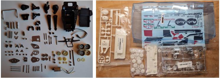
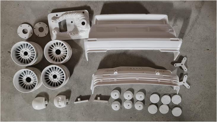
Picture of the main parts, some observations: – at the bottom right almost in the corner are the 4 rims, – the electronics box and front bumper are intact; they have several scratches and cuts, – the gears look new, as if they had never run the model; given the state of wear of the plastic tub chassis, it is easy to assume that they were replaced at a later date, – inside the box in the gearbox were the two plastic bands to secure the battery, The image on the right shows all the material needed to complete the restoration: Lexan body, stickers, various sets to modify to create the missing parts.
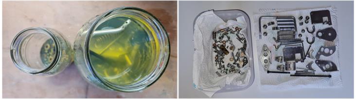
The next step is to wash the various components that have been divided into metal and plastic parts. The treatment of the parts varies according to the material, for metal parts the preparation is as follows: soak the parts for a week in a container with diesel oil, which has the task of degreasing and removing rust. It is best to divide the parts according to size: small parts in the container on the left and large parts in the container on the right (picture on the left). Use glass jars with iron stoppers that can be closed during treatment to prevent the diesel vapours from impregnating the air (picture on the left). After one week; rust, grease, dirt, oxidation have been removed. Finally, clean the parts by wiping off the diesel with a kitchen paper towel and place the metal parts on a sheet of kitchen paper to expose them to the sun for a few hours so that the diesel evaporates completely (image right).
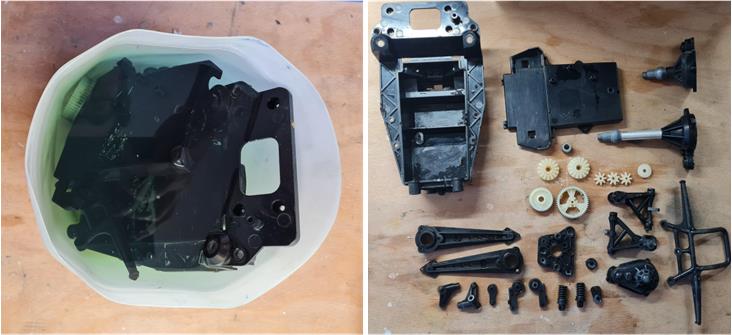
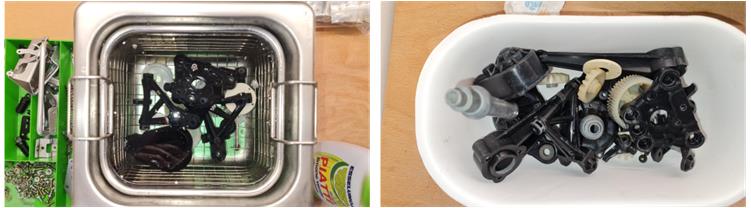
For plastic parts, preparation is as follows: soak all parts for a day in a container with water and plenty of dish soap (left image).The purpose of the soap is to degrease the parts and remove dust residues (image on the right); after the day of immersion, rinse with warm water and scrub using a toothbrush with hard bristles to remove any residual dirt.
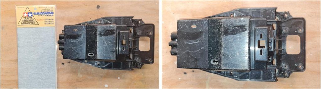
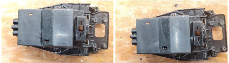
The plastic parts definitely look better.The washing revealed that the central tub of the frame in the lower part has scratches due to impacts with the road surface, these scratches are quite deep: polishing is not sufficient, but a treatment with abrasive paper is necessary. The use of abrasive paper involves several processing steps, starting with the lowest number and then moving on to the highest number. If the scratches are deep, consider starting with 600 or 800 abrasive paper; with such rough abrasive paper there is a risk of damaging the part further by increasing the scratches. Test the effect of the sandpaper in a corner and assess which is the most suitable sandpaper to start work with. For best work on plastic, treat the part with wet sandpaper. For this work, 1,200 grit paper is sufficient. The procedure is as follows: – completely immerse the piece of sandpaper in water and wet the surface to be treated, – work the surface to be regenerated until the paper dries, – when the abrasive paper is no longer wet, the friction between the surface and the paper increases; completely immerse the paper in water again, – repeat this operation until the surface to be treated reduces the number of scratches. The picture on the left shows the workpiece before machining and on the right the result after machining the surface with 1,200 grit sandpaper.The surface has become matt, but many marks have been removed,
– When the surface reaches a better surface finish and most of the scratches have disappeared, repeat steps above with 1,500 paper (left image) and then 2,000 (right image),
– polish the entire tub frame using polish or toothpaste. In this way, all plastic parts have the same surface finish (image right).
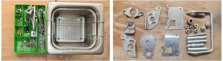
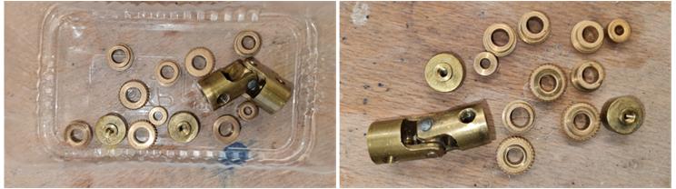
Metal and plastic parts are ready to be placed in the ultrasonic machine. To avoid metals reacting chemically with each other, separate brass, steel, aluminium… and wash them separately. The process for parts depends on the material: – wash all small parts and metal parts with the ultrasonic washing machine for a time of 25 minutes at 70°C. In the picture on the left you can see the metal parts divided by material type and the ultrasonic machine ready for use. In the image on the right you can see the aluminium parts after washing. Despite the treatment with diesel and the ultrasound machine, signs of wear and tear on the metal remain evident; these can be removed with a good polish.
The treatment with diesel and ultrasonic machine had an excellent result on bushings and bronze parts in general, which returned to new. The picture on the right shows the parts at the end of the treatment,
– Rinse the freshly treated parts with warm water and dry with a paper towel, – polish larger parts (such as the metal plates for the electric motor system – differential and bumper plate) with polish or toothpaste.
For plastic parts the procedure is very similar:
– wash all plastic parts (steering and front suspension components) and Teflon (gears) with the ultrasonic washing machine for 25 minutes at 40°C. The picture on the left shows the car ready with green coloured water indicating the presence of kitchen soap. The picture on the right shows the parts after washing, dirt and stains were removed by the action of the ultrasonic cleaner, which could do nothing against marks and scratches caused by the use of the model.
– rinse the freshly treated parts with warm water and dry with a paper kitchen cloth, – polish the larger parts with polish or toothpaste.
The rims have remnants of the glue used to secure the tyres. Use a flathead screwdriver and/or a box cutter to remove the rubber and glue residues. It is impossible to remove all the black pieces of rubber, but the ultrasound machine removes the last glue residues from the rims.
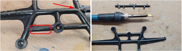
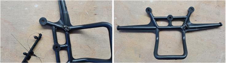
The bumper has a partial break (indicated by the red arrow in the picture on the left) between the right whisker and the central body and has certainly seen better times. The body is clearly marked ‘Tamiya Quattro’ (red box in the picture on the left) and this marking is not always present. So it is correct to try to recover the part by gluing the moustache to the central body. The most efficient technique to repair such damage is to use cast plastic. Hot-melt glues, two-component glues or others do not have the same elasticity as plastic: using these binders, the crack would reform at the first deformation. The technique of melting plastic imposes the use of all possible precautions to avoid breathing in plastic fumes; if not performed correctly, it subjects the person to vapours that are definitely not good for the health. This technique can only be mastered if one has excellent dexterity and a well-ventilated room in which to work in a constant flow of air that draws in the plastic vapours. Plastic melt method – Heat a piece of plastic taken from a scrap Tamiya set, the aim is to work with a material that is the same plastic as the chassis is made of. To heat the piece of plastic use the soldering iron for tin, changing the tip to a blade insert that has two tasks: melt and position the plastic (see image on right)
– Heat the end of the part to be sacrificed, you will get melted plastic on the tip of the soldering iron. During this operation be very careful of fumes: only work in a ventilated room with fume extraction. – open the break by bending the moustache and insert the melted plastic between the two parts to be joined; the plastic brought back with the tip of the soldering iron melts with that of the part to be repaired
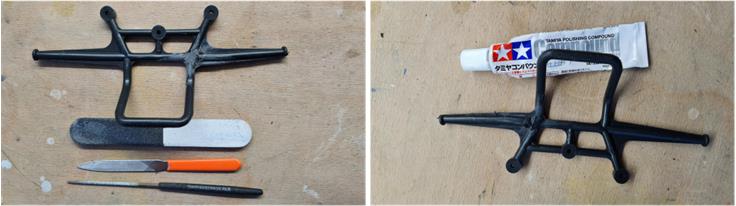
– wait 24 hours for the plastic to solidify, – work the repair with iron files of various shapes to remove excess plastic, at which stage shape the added plastic back to its original shape – polish the part with polish or toothpaste.
From a mechanical point of view, this repair restores the part to its original condition. If the repaired part does not satisfy from an aesthetic point of view, it is possible to paint the part. If you are not satisfied with the aesthetics, apply a coat of Tamiya’s ‘surface primer grey’ that is more ‘robust’ than Tamiya’s ‘fine surface white’ and then apply the TS82 colour ‘rubber black’. The construction phase of the model is relatively simple; sequence of pictures showing the stages in which the chassis is assembled:
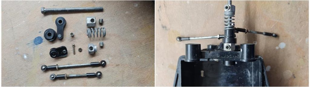
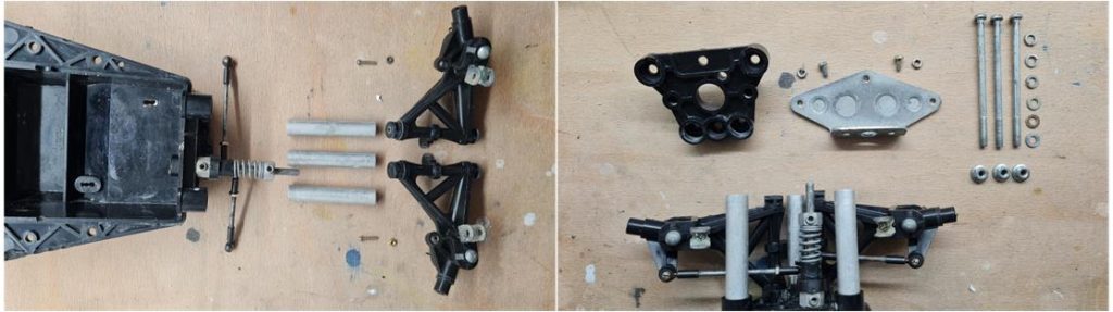
– preparing all the necessary parts for the steering. This model is equipped with the steering arm ball joints that are installed on few Tamiya models. Pay particular attention to the correct length of the steering arms because the geometry of this suspension is very sensitive. Incorrect length of the arms causes incorrect toe-in, which worsens when the suspension is compressed, – install the steering system on the central tub of the chassis,
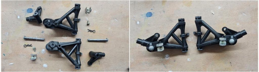
– assemble the front suspension; the front arms are a part that is subject to wear and tear in heavy use of the model. Check for cracks that were not noticed when cleaning the parts,
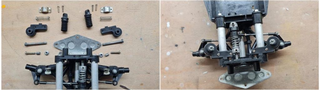
– Assemble the frontal system comprising suspension, steering system and bumper support. Lubricate the rotating parts for both suspension and steering system,
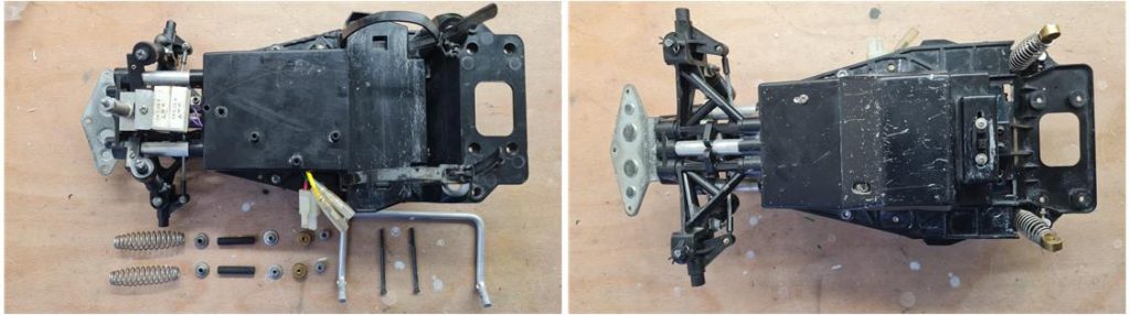
– the front suspension action relies solely on the springs. The suspension pins have an original attachment system to the two front tubes that remains typical for the Wild Willy and Quattro chassis. With the introduction of the Quattro chassis the system has been updated and this innovation is also introduced in the Wild Willy second series long wheelbase chassis. With this part the front chassis is complete, only the plastic bumper is missing,
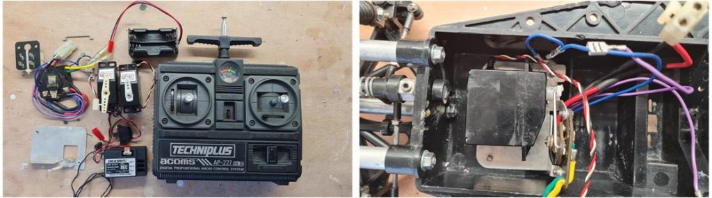
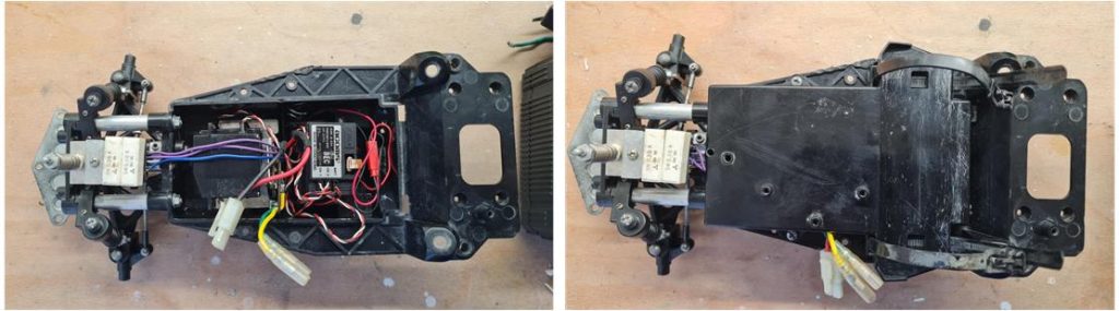
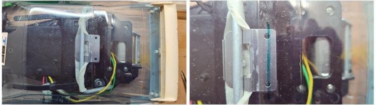
– electronics is Acoms from the same period as the model. Install electronics starting with the speed control servo that is installed on the metal plate,
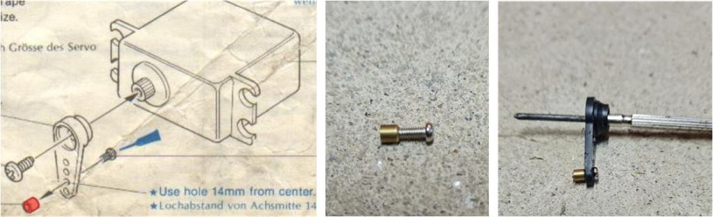
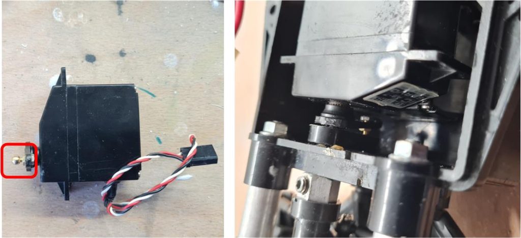
– the pin highlighted in red in the picture on the left is rarely available in models to be restored, however, its presence can only be verified after dismantling the model. In this restoration it is present; the picture shows how small it is.
If it is missing, it can be replaced with a 4 mm diameter ball pin (highlighted by the red frame in the left image). The image on the right shows the installation of the ball pin and how it works correctly with the steering lever.
– install all the electronics and then close the tubular frame shell using the top cap. Pay attention to the cables, which have their own cable grommets,
– Prepare all parts for the rear suspension and roll bar. Install all parts on the centre shell of the chassis,
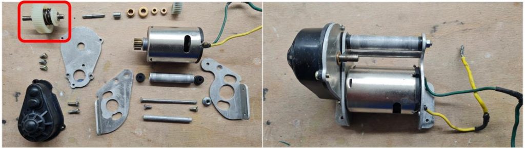
– assemble the rear drive system, which also includes the clutch, the upper right part highlighted by the red frame in the picture on the left. The clutch is pre-assembled at the factory. The transmission system is very solid and the gears are oversized to withstand the most rough use,
-assemble the rear axle and the electric motor-transmission system to the chassis. Now the chassis is complete and ready to marry with the body (image right).
Body restoration
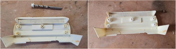
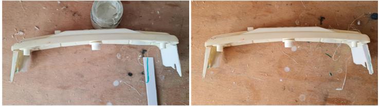
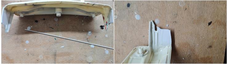
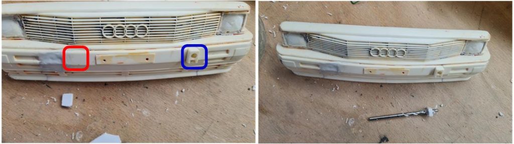
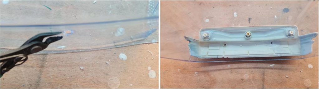
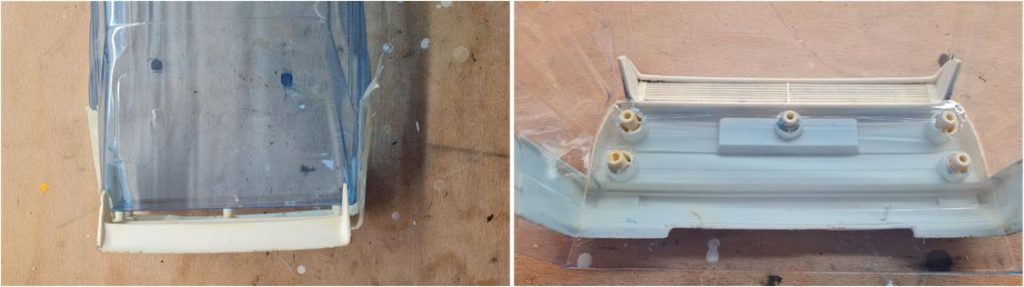
The Lexan body is absent as are some of its styrene parts: – three + three front lights – two rectangular ventilation grilles on the bonnet and – top-hat shaped blocks that fit inside the body to attach front bumper with front grille – bumper with rear wing to the body. The front bumper grille and rear wing bumper are present, but are damaged. Today (2024) Tamiya no longer produces the body for Audi Quattro, the Lexan body can be found on the market from a well-known manufacturer of Tamiya body reproductions. In order to be able to complete the body, it is necessary to first repair the rear and front accessories and then rebuild the missing parts. A good starting point is part number 19008156 whose description is ‘B parts for Volkswagen Golf Mk.1 Racing Gr.2’ (left in the picture). The hat-shaped blocks are missing for the bumper with front grille and for the bumper with rear wing. It is possible to fit the top-hat shaped blocks from the set 19008156: these blocks have a hole with a diameter of 5.5 mm (highlighted in red in the picture on the right) which is smaller than the tower on both the front and rear bumper (highlighted in blue in the picture on the right) which has a diameter of 6.5 mm
It is necessary to enlarge the hole on the top-hat shaped block: manually enlarge the hole using iron drill bits first 6 mm in diameter and then 6.5 mm in diameter. After enlarging the hole, test the result by installing the block on the rear bumper tower. Test that the blocks fit into the pins without offering resistance or offering minimal resistance: it is the screws that hold the two parts in place, it is not the joint between the pin and the block that holds the parts in place. There are five rear bumper pins, so repeat the operation above five times.
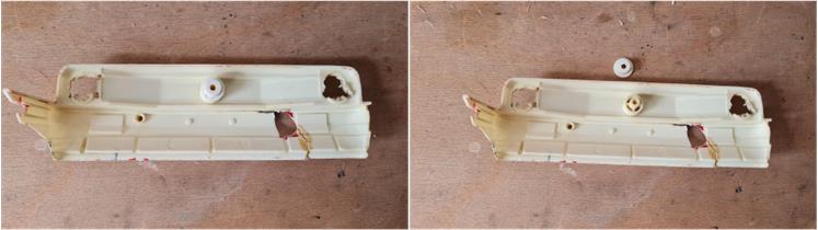
Repeat the same operation for the only pin in the front bumper: the centre one (in the picture on the left the block is installed on the tower in the centre of the bumper, in the picture on the right the block is just above the bumper). The other two towers have to be rebuilt because they are missing. In total, therefore, five plus one top-hat shaped blocks were prepared.
To proceed to the next step of restoring styrene parts, prepare three containers containing
– Pure Acetone – Acetone and ABS with a predominance of Acetone. This solution is very liquid and is best used for joining large, even surfaces or penetrating into cracks. – Acetone and ABS with a predominance of ABS. This solution is very dense and finds its best application for joining small parts that need to be welded onto a surface, the drop of solution remains where it was laid. The denser solution is also good for the construction of parts that have been lost or destroyed.
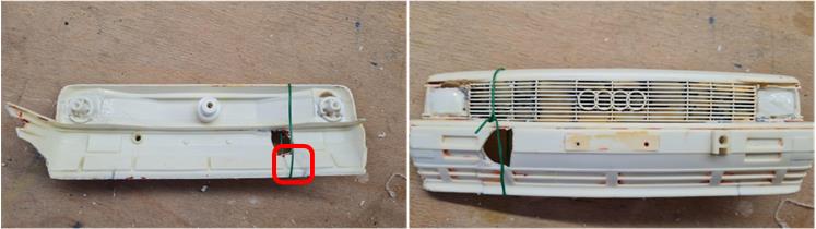
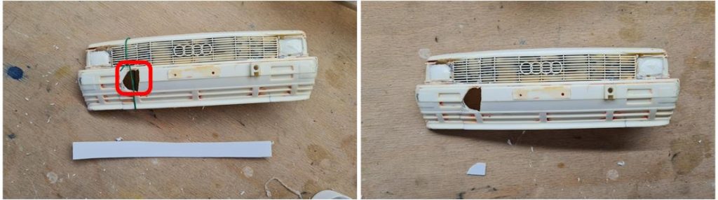
Acetone acts chemically on plastics by dissolving ABS and Styrene; repairs are therefore a weld that has the same mechanical strength as a new part. For the bumper with front grille, various repairs and reconstructions of entire areas are necessary; it is the body component that has suffered the most from the passage of years and has obviously been mistreated. Any poor restoration result for this part would invalidate the restoration of the entire model, which is why we start with the front grille bumper. The bumper has a crack in the lower right part highlighted in the red frame of the picture on the left. Sequence of operations to repair this irregular crack: Spread a veil of Acetone on the fracture line using a brush. Acetone enters the fracture and welds the two parts, Acetone alone does not offer sufficient mechanical strength; before Acetone evaporates spread a veil of Acetone and ABS solution in the more liquid formulation so that it penetrates the fracture. The function of pure Acetone alone is to prepare the surfaces for the welding that is performed by the solution. The function of the Acetone and ABS solution is to give mechanical strength to the repair. The solution solidifies by welding the two parts, which are held in place by a wire (green colour in the picture on the right). Apply Acetone and ABS solution to both the inside and outside of the bumper. After 24 hours the welding process is complete.
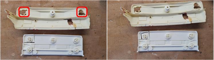
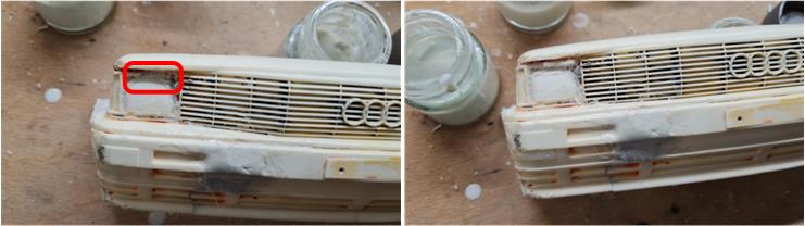
It is necessary to rebuild the two headlights that are missing. This part is quite complex because on the inside, at the headlights, there are the towers that fit together with the top-hat shaped block that is used to install the bumper with styrene front grille on the Lexan body. Sequence of images illustrating how to rebuild from the Golf bumper part of set number 19008156:
– the missing parts are highlighted by the two boxes in red; these are the two headlights, – cut out the corresponding part of the headlight from the front bumper with grille of the Golf, which also includes the pin for the top-hat shaped block,
– The person who did the job of removing the headlights from the Audi drilled 2mm holes around the perimeter of the headlight itself and then simply ripped out the parts. So there is no regular shape to be reproduced to fill the hole, it is necessary to proceed in small steps by cutting the piece out of the Golf bumper and then, using 180 grit sandpaper, reduce the size until the new piece fits perfectly into the hole in the front mask,
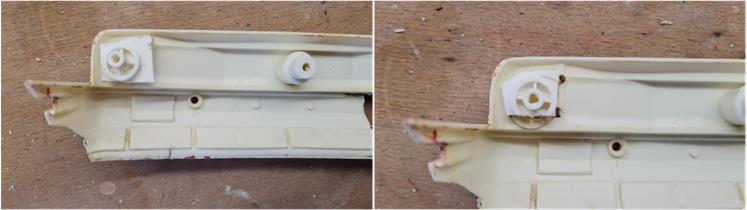
– repeat the same operation for the left and right side thus obtaining the two pieces to be inserted in the front mask of the Audi, – on the bumper of the Audi on the inside there are two circular sectors which is what remains of the base of the tower for the cylindrical block; use those as references to cut out the missing parts and test the installation by checking that they fit well at the rear (picture on the left) and at the front (picture on the right),
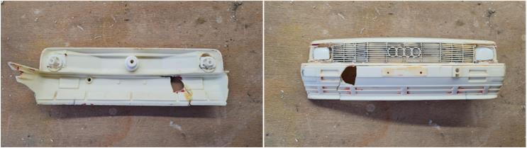
– when the two parts fit perfectly into the bumper, spread a thin layer of Acetone along the joint lines of the new headlights both internally and externally using the brush. Acetone must penetrate inside the joints, – before Acetone evaporates, spread a thin layer of less dense Acetone and ABS solution along the joint lines of the new headlights both internally (image on the left) and externally (image on the right) using the brush. The solution must penetrate inside the joints, – wait at least 24 hours for the solution to solidify,
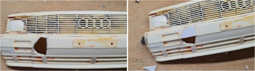
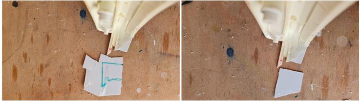
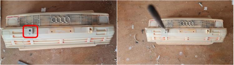
Sequence of images illustrating how to proceed with the reconstruction of the missing bumper part (red box in the image on the left). The damage is broken up and irregular on a surface that is not flat; it is better to proceed with the repair in two stages, dividing the upper part from the lower part which are slightly inclined to each other:
– cut a strip of ABS from a sheet with a thickness of 1 mm, – cut from this strip of ABS an irregular trapezium that has the same dimensions as the damage in the upper part (image on the right)
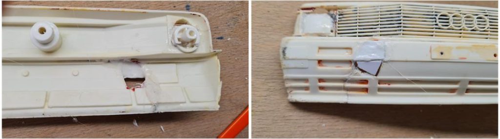
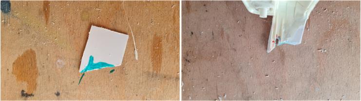
– when the shape of the trapezium allows it to fit perfectly into the bumper, spread a thin layer of Acetone along the joint lines using the brush. Acetone must penetrate inside the joints, – before Acetone evaporates, spread a thin layer of less dense Acetone and ABS solution along the joint lines using the brush. The solution must penetrate inside the joints. The thin layer of Acetone and the solution are the base on which the ABS trapezium will adhere to the Styrene bumper remaining in the position in which it must be welded (image on the left). Acetone and solution take some time before acting so you have all the time necessary to best position the trapezium, – reinforce the repair by passing a thin layer of Acetone with ABS solution in the most liquid version on the inside and outside; before applying another coat wait for it to start to form a solid surface layer, – once the trapezium is positioned, you can cut the triangle from the 1 mm high ABS strip to repair the lower part of the bumper (image on the right)
– when the shape of the triangle allows it to fit perfectly into the bumper, spread a thin layer of Acetone along the joint lines using the brush. Acetone must penetrate inside the joints, – before Acetone evaporates, spread a thin layer of Acetone and ABS solution less dense along the joint lines using the brush. The solution must penetrate inside the joints.
– the triangle-shaped break had very jagged edges so, after a day, strengthen the joint by applying more coats of a less dense solution. Wait at least half an hour between one application and the next; the indicator that the surface is ready for a new treatment is the formation of a solid surface veil, only now is it possible to apply the next coat. The veil must be thick enough not to break when it comes into contact with the brush for the next coat. It is better to be patient and wait longer to avoid the repair having air bubbles inside it that make it less robust.
– the double repair is ready to be worked with sandpaper.
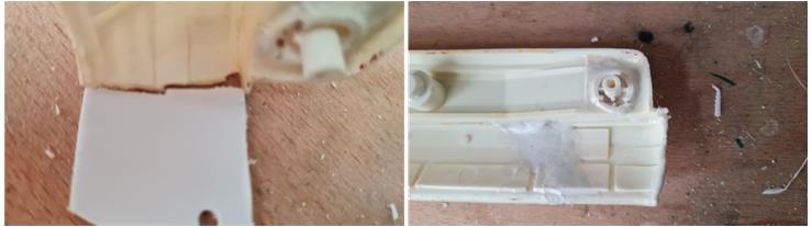
Above the right headlight there is a hole that needs to be repaired (see red box in the left image). The sequence of operations to be performed to reconstruct this part: cut out a piece from a 2 mm thick ABS sheet that has the same shape to be repaired, spread a thin layer of Acetone on the walls of the hole with a brush, (before Acetone evaporates) spread the dense solution on the walls of the hole with a brush, place the part just cut into the hole, spread the more liquid solution along the perimeter of the part just inserted so that the solution penetrates along the joint line from both the front and rear.
The lower left side of the front bumper is missing. Sequence of operations to be performed to proceed with the repair: cut out a piece from a 1 mm thick ABS sheet that has the same shape to be repaired using the bumper itself as a template, marking the outline with a marker (left image), spread a thin layer of Acetone on the walls of the bumper along the joint with a brush, (before Acetone evaporates) spread the dense solution on the walls of the bumper with a brush, position the part just cut, spread the more liquid solution along the perimeter of the panel so that the solution penetrates along the joint line from both the inside and outside. The solution now takes effect by welding the two parts and after a day the repaired part is ready to be worked with sandpaper.
The right side of the front bumper is missing. Sequence of operations to be performed to proceed with the repair:
– Use the left side as a template. The portion to be repaired has a complex irregular shape so cut a trapezium from a 1 mm high ABS sheet a piece that has the same maximum dimensions,
– using the bumper itself as a template, mark the outline with a marker (image on the left) to reduce the size of the trapezium to that of the piece to be welded to the rest of the bumper; compare the new part just built with the left side that is present. The two parts must overlap perfectly (image on the right),
– shape the joint line as best as possible so that the two parts fit together (image on the left), – spread a thin layer of Acetone on the walls of the bumper along the joint with a brush, – before Acetone evaporates, spread the thick solution on the walls of the bumper with a brush (image on the right),
– position the part just cut, spread the more liquid solution along the perimeter of the panel so that the solution penetrates along the joint line from both the inside and outside (image on the left), – using the left side as a template, mark the upper flap that acts as a reinforcement on the 1 mm thick ABS sheet with a marker (image on the right),
– apply along the joint line with a brush first Acetone and then a thick solution of Acetone and ABS, – cut out the part and apply the part in its position,
The solution works by welding the parts and after a day the repaired part is ready to be worked with sandpaper. The two internal reinforcements of the right side of the bumper are still missing. Sequence of images that summarizes how to build this part: use the right side as a reference, cut two strips from a 2 mm square section ABS bar that are as long as the missing part, apply Acetone with a brush to the point where the two reinforcements are missing and position the pieces just cut. Acetone works by welding the parts and after a day they are ready to be worked with sandpaper.
To complete the repair of the left headlight, you need to reapply the upper lip (see red box in the image on the left). Sequence of images that summarizes how to build this part: cut a piece from a 1 mm square section ABS bar that is as long as the missing part, apply Acetone with a brush to the point where the upper lip is missing and position the piece just cut. Acetone welds the parts and after a day they are ready to be worked with sandpaper.
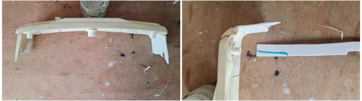
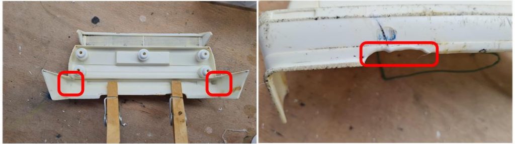
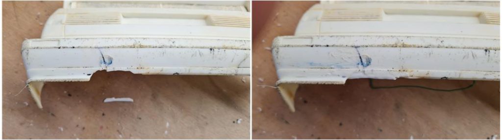
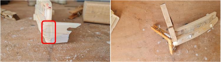
The bumper with rear spoiler has several fractures (two fractures are highlighted in the red boxes in the image on the left) that can be repaired by applying a thin layer of Acetone and a less dense solution. To keep the parts in place during the welding process, use wooden or metal clothes pegs (avoid plastic clothes pegs because Acetone would weld them to the part to be repaired). The lower lip has a part that is completely missing (highlighted in the red box in the image on the right).
Sequence of operations to be performed to proceed with the repair: cut a strip from a 1 mm thick ABS sheet that replicates the missing part, spread a thin layer of Acetone along the fracture line using a brush, (before Acetone evaporates) spread the denser solution along the fracture line using a brush, join the two parts, spread a thin layer of less dense solution along the fracture line so that it penetrates between the parts and welds them. After a day, the repair is ready to be worked with sandpaper.
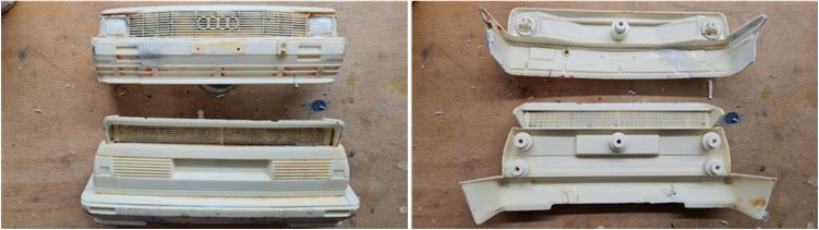
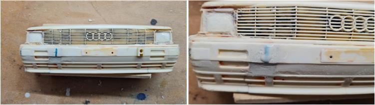
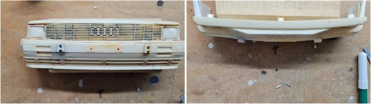
The front bumper with grille and the rear bumper with spoiler are now ready to be worked with metal files, the parts to be worked are very limited and it is better to use small flat and circular iron files. In the images below you can see the two bumpers before working with the files
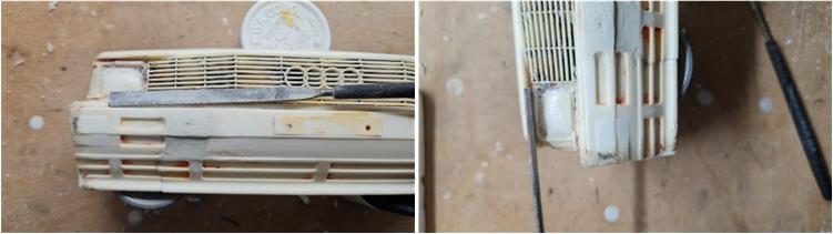
Work with files every portion where repairs have been made; for example:
– work the upper edge of the bumper (image on the left) with the flat file that runs along the bumper itself to mark the step, – use the same file to work the bumper at the height of the trapezoid-shaped repair to make it flat compared to the rest of the surface and perform the same operation with the lower part at the height of the triangle-shaped repair that is slightly inclined. Avoid using files that are too large to avoid accidentally working the nearby parts, – define the upper edge of the headlight (image on the right) using the line cut so that it fits into the line to be defined,
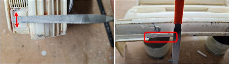
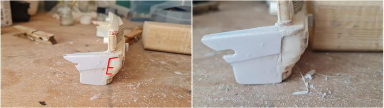
– define the four sides of the headlight by moving the file along the boundary line; for example, in the left image the movement defines the upper inner lip of the right headlight, – define all the added surfaces; for example, in the right image the processing of the rear lower lip is highlighted in the red box.
Work with metal files all the parts that have been repaired or added in the previous steps following the techniques described above. In the image the bumpers after the work: the more defined contours obtained with the files are evident, the repaired surfaces have continuity with the rest of the bumpers.
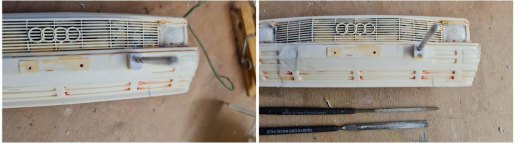
The right side support on the front bumper is completely missing (highlighted in the red box in the image on the left) which has the hole for installing the additional lights. Sequence of images that summarizes the operations to be performed to proceed with the repair:
– cut out a rectangle from a 2 mm high ABS sheet that has the same dimensions as the left side support (highlighted in the blue box in the image on the left) – with a 2 mm iron tip make a hole using the left support as a template, – widen the hole with a 3 mm diameter iron tip (image on the right)
– using the drill bit as a pin, overlap the rectangle thus obtained to the one on the left side; shape the new support with iron files giving it the same shape as the original part,
– use the left side pin as a reference to determine the position of the right pin and mark the point with a marker (left image). Apply Acetone with a brush (right image) and position the newly built piece.
– check the correct positioning of the plate both externally (left image) and from below (right image) or from above. Acetone takes several minutes to set and therefore you have all the time necessary to position the pin in the correct place.
– after 24 hours, the support is welded to the bumper and you can finish the sides of the pin with an iron file (picture on the left in the red box) – with a 3 mm iron bit, make the through hole in the front bumper (picture on the right, a circular section file is inserted into the hole).
On the left side of the front bumper there are grooves that follow the shape of the bumper, on the repaired right side these parts are completely missing. Using the left side as a template, cut out the side shape from a 1 mm thick ABS sheet. Apply pure Acetone to the side of the piece just built and join it firmly to the right side wing of the bumper. Use wooden pegs to hold the parts together and give the Acetone time to weld them (see image on the right).
After 24 hours, the piece is fused with the entire bumper (see image on the left) and you can work the surface with a metal file. Go over the demarcation lines (highlighted in red in the image on the left) several times to highlight them more (image on the right).
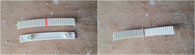
The two grilles on the hood are missing, which can be obtained from the set 19008156 where there is a very long grille. To obtain the two small grilles, divide the grille along the red line highlighted in the image on the left: the two grilles thus obtained have the right length to fit on the Lexan body of the Audi Quattro.
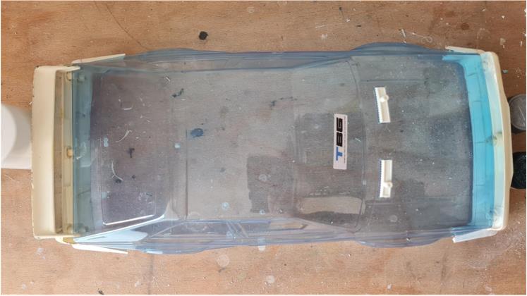
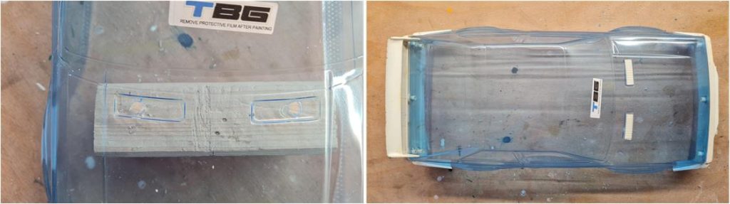
Now you can test the installation of the two hood grilles, the front bumper with grille and the rear bumper with spoiler on the Lexan body.
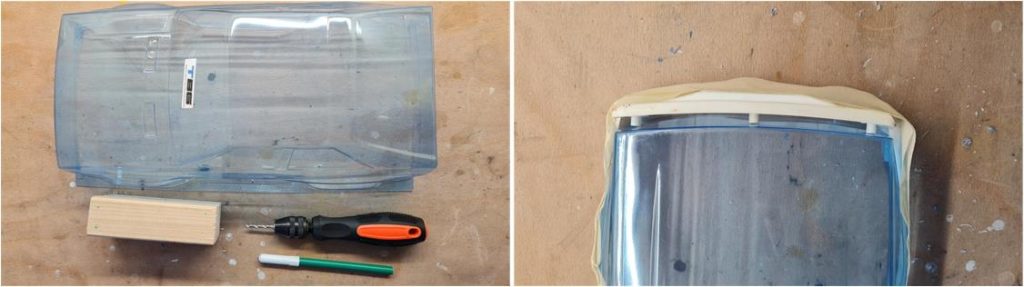
The Lexan body is not pre-drilled, so you need to proceed with caution when making the holes for the installation of the two bumpers and the grilles on the hood. Making a mistake in making a hole is equivalent to having to change the Lexan body, only the front and rear parts in Styrene are large enough to hide any small errors. Sequence of images illustrating how to proceed with drilling the Lexan body in correspondence with the bumper fixing towers:
– the necessary tools are a marker, a hand drill, iron drill bits with a diameter of 3 mm – 4 mm – 6 mm – 8 mm, a piece of wood, – position the front bumper on the body in the exact position in which it will be installed and block the two parts with paper tape (image on the right),
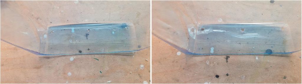
mark with the marker the three points where the front bumper towers touch the Lexan body, – detach the front bumper from the body, – drill the three holes with the 3 mm bit (left image). Drill the holes from the outside and position the piece of wood inside to prevent the Lexan body from bending and preventing the bit from piercing the surface. Drilling from the outside inwards is intended to leave the best finish on the external surface. At this stage, you can check that the three holes are in the right position by comparing the bumper towers and the holes in the body. If you have not done a good job this is the right opportunity to try to understand if in the next steps it is necessary to make corrections by enlarging the hole in the right direction, – enlarge the holes with the 6 mm tip and check the position of the holes in relation to the bumper, – enlarge the holes with the 8 mm tip (image on the right), – position the front bumper on the body, block it temporarily, mark the two side holes with the marker and drill the body with the 4 mm tip using the same technique used previously which involves supporting the piece of wood inside to support the Lexan which would deform under the pressure of the tip,
– refine the Lexan by cutting off any burrs that the drill bits leave unfinished on the body (left image); every angled curve and cut can be a point where a crack will propagate through the Lexan body in the event of an accident. Avoid leaving sharp corners and cuts, – test that everything has been done correctly by joining the two parts that should fit together even without the top hat supports (right image)
– perform the same operations for the bumper with rear wing. Pay more attention to this part which has 5 fixing towers. To practice and understand the technique, start from the bumper with front grille which has only three fixing towers and the operation is simpler
– drill the two holes for the grills on the hood. As for the other holes, always place the piece of wood to support the cutting of the tip (left image) – test installations of all parts on the body (right image)
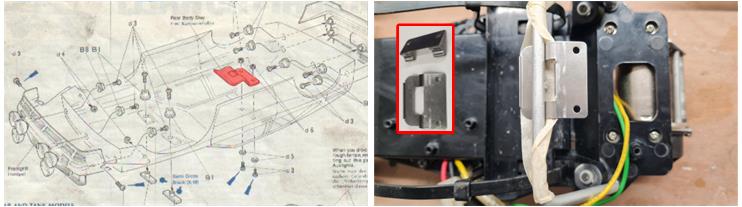
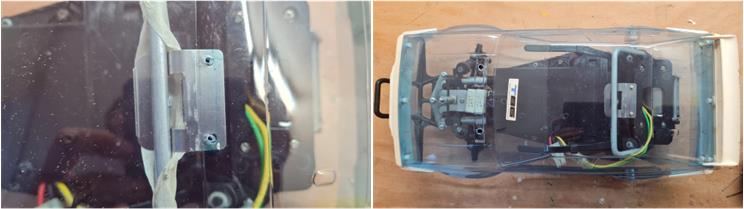
To lock the body to the chassis, there is a shaped metal block at the rear that fits onto the aluminum roll bar; this part is no longer available and is not easily found on the spare parts market. It is possible to replace this part (highlighted in red in the image on the left) with a similar plate that is used in the Sand Scorcher replicas; set number 19808269 identified as “Tamiya Mounting Plate A & B for Sand Scorcher”. This plate is larger than the starting one, therefore, it is necessary to find where to drill the two 2 mm diameter holes to lock the plate to the Lexan body. Lock the plate 19808269 to the roll bar with scotch tape so that it remains in the desired position (see image on the right).
Place the body on the chassis, use the front tower hole as a reference, which is indicated on the body as a small hill. Take the measurements and mark the line that joins the two holes (left image). Take the measurements so that the two holes of the plate are positioned in the center of the body, drill the Lexan body using 2 mm diameter iron drill bits and a piece of wood as a support.
After drilling the two holes you can install the plate using the two screws with their bolts (left image). Drill the 2.2mm hole for the front tower and then test that the body fits correctly (right image).
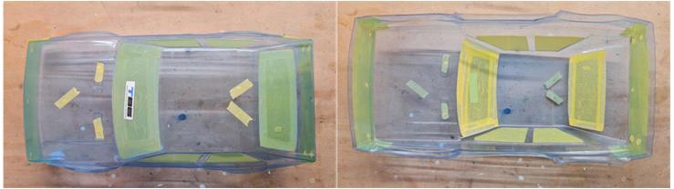
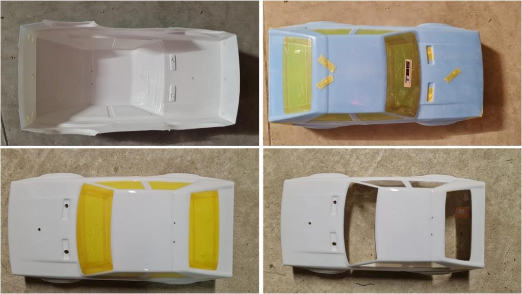
Prepare the body for painting:
– internally mask the side windows, the windshield and the rear window (left image) – externally close all the holes to prevent paint from coming out; 3 holes in the front bumper, 1 hole per side to fix the front bumper wheel arch, 1 hole in the front tower to fix the body to the chassis, 1 hole for each of the two bonnet sockets. 2 holes for the central plate to fix the body to the roll bar and 5 holes in the rear bumper (right image).
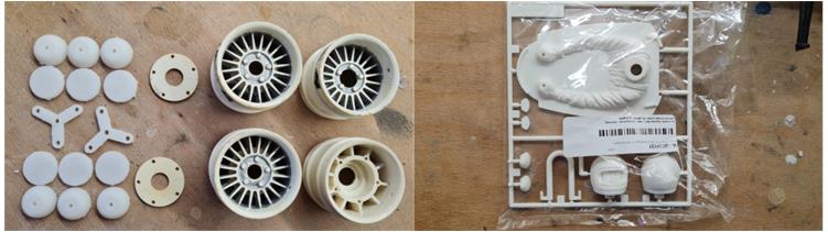
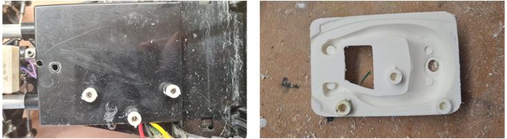
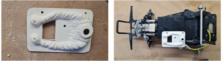
Prepare the styrene pieces for painting by applying the white primer. The pieces to be treated are different and are visible in the image on the left. The model is missing the driver. To rebuild it, it is necessary to start from a driver that is as similar as possible and in the same scale which is 1\10 (image on the right). The driver present in the set 19008156 does not have the right shape in the hands, this driver can be used for the restoration of other models such as Porsche 934 number 58001, Porsche 935 number 58002 and Lamborghini numbers 58005 and 58008…. Today (2024) the driver for the Tyrrell 6 wheels is available on the market which is very similar, code 10004131 defined as “G Parts” for the model 49154. From this part, the body of the driver and the helmet composed of two half shells are to be used. The roll bar and the rearview mirrors are to be kept for future restorations; for example, the mirrors are installed on Porsche 934 models 58001, Porsche 935 models 58002, Tyrrell P34 models 58003, Porsche 936 model 58006, Toyota Celica LB turbo model 58009, Lamborghini Countach model number 58005 and in the CS version model number 58008.
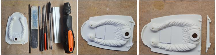
The tools needed for this process are (left image):
– Acetone, – dense Acetone and ABS solution, – less dense Acetone and ABS solution, – iron files of various shapes and sizes, – hand drill, – hacksaw, – pen, – ruler.
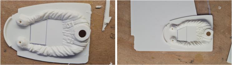
The base of the Tyrrell P34 driver is different from that of the Audi Quattro; therefore, the modifications must be concentrated mainly in this part. Sequence of images showing how to proceed with the modification:
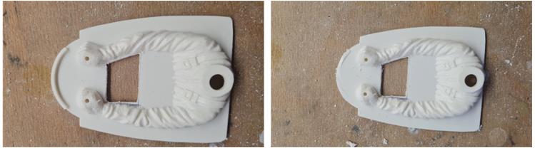
– mark the central trapezoid-shaped hole that is missing in the version for the Tyrrell P34, – the base has an oval shape and must become rectangular, the larger base of the oval is longer than the long side of the rectangle. Mark the line where to make the cut to reduce the size of the oval. When an original driver is not available, then determine the proportions from the photos of the instructions of the model installed on the Audi Quattro to deduce the dimensions and cutting lines (right image),
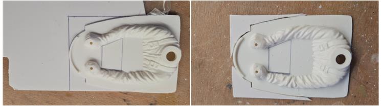
– cut the two tabs that stick out on the back side to the right and left of the driver and work the surface with the flat file (left image), – place the driver on a 2 mm thick ABS sheet to delimit the parts to be added to the oval to obtain the starting rectangle. Not having the original from which to take the dimensions, build a rectangle of larger dimensions and then work it to obtain the correct proportions (right image),
– cut the two wings to transform the oval into a rectangle, work these two parts with the iron files until the shapes fit together like a puzzle (right image). It doesn’t matter if they fit perfectly, the Acetone and ABS solution fills the empty parts,
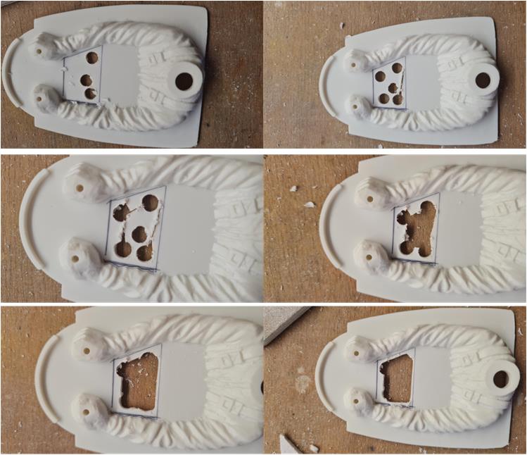
– work the central trapezium with a 6 mm diameter drill bit, make holes at the four corners and at least one in the center. These holes allow you to insert the metal marker and cut the desired shape while staying away from the marking lines to avoid cutting too much,
– once the hole is made, work the four sides with the flat metal file to obtain the marked trapezium (left image), – cut the crescent-shaped lip present in the front part (right image),
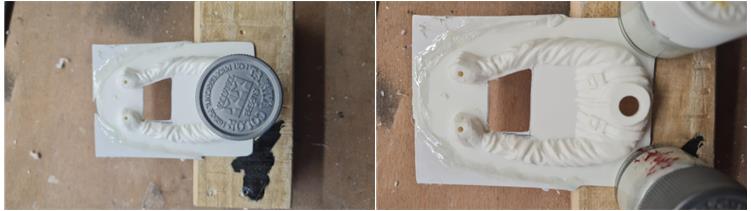
– apply a thin layer of Acetone with a brush on the joint lines, – before Acetone evaporates, apply the dense Acetone and ABS solution on the joint lines. The dense solution adheres where it is applied and therefore it is easy to join the two parts (left image). After 24 hours, the solution has melted and welded the parts together, it is possible to add missing pieces. Build and weld the small missing piece in the middle of the short front side (right image). The goal is to obtain a large rectangle to reduce to the correct size
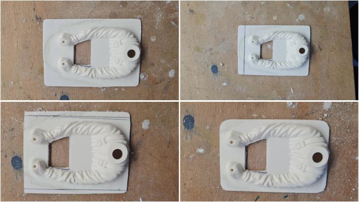
– work the rectangle laterally, above and below with the iron file or 400 – 600 sandpaper in such a way as to obtain a smooth surface to the touch, – mark the lines in such a way as to reduce the area of the rectangle both on the short side (image number 2) and on the two long sides (image number 3), – perform the cut with the iron saw and then work the sides with the iron file or 400 – 600 sandpaper in such a way as to replicate the original shape which has rounded corners (image 4),
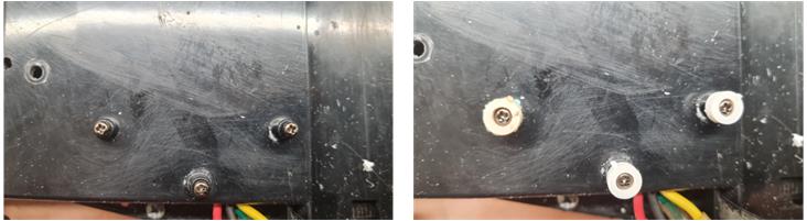
– you need to add the three towers in the lower part of the driver base corresponding to the three screws on the frame to fix the driver itself. Screw 2 mm diameter screws into the 3 mm holes in the frame (photo on the left). Position the three cylinders that fit on the head of the screws, the cylinders are three shims taken from some leftovers from previous restorations. They are spacers that are often present in Tamiya parts; in set number 19008156 there are several,
– apply a thin layer of thick solution on the perimeter of the cylinders (left image), – place the driver over the towers, – the solution immediately joins the towers to the base of the drivert enough to be able to move them from the frame and let them rest long enough for the parts to become one piece (right image), – to consolidate the parts apply the less thick solution of Acetone and ABS around the towers where they touch the base, – remove the 2 mm screws from the frame that have served their purpose,
– drill the three holes corresponding to the towers using the hand drill. The first operation is to drill the base with a 1.5 mm bit, check that the holes are in the correct position and then widen the holes to 3 mm (left image), – try installing the driver on the frame with the 3 3 mm diameter screws (right image).
To prepare the styrene parts for painting, apply several coats of Tamiya’s fine white primer in the “Fine Surface Primer L White” version. The primer must completely cover all the surfaces evenly and prepare them for then applying two coats of TS26 “Pure White”.
For the body, apply several coats of PS1 White. The body is then ready to remove both the internal masking and the external light blue film.
Assemble the front bumper with front grille, the rear bumper with spoiler, the two grilles on the bonnet and apply the stickers.
Assemble the wheels and then install them on the frame together with the driver.
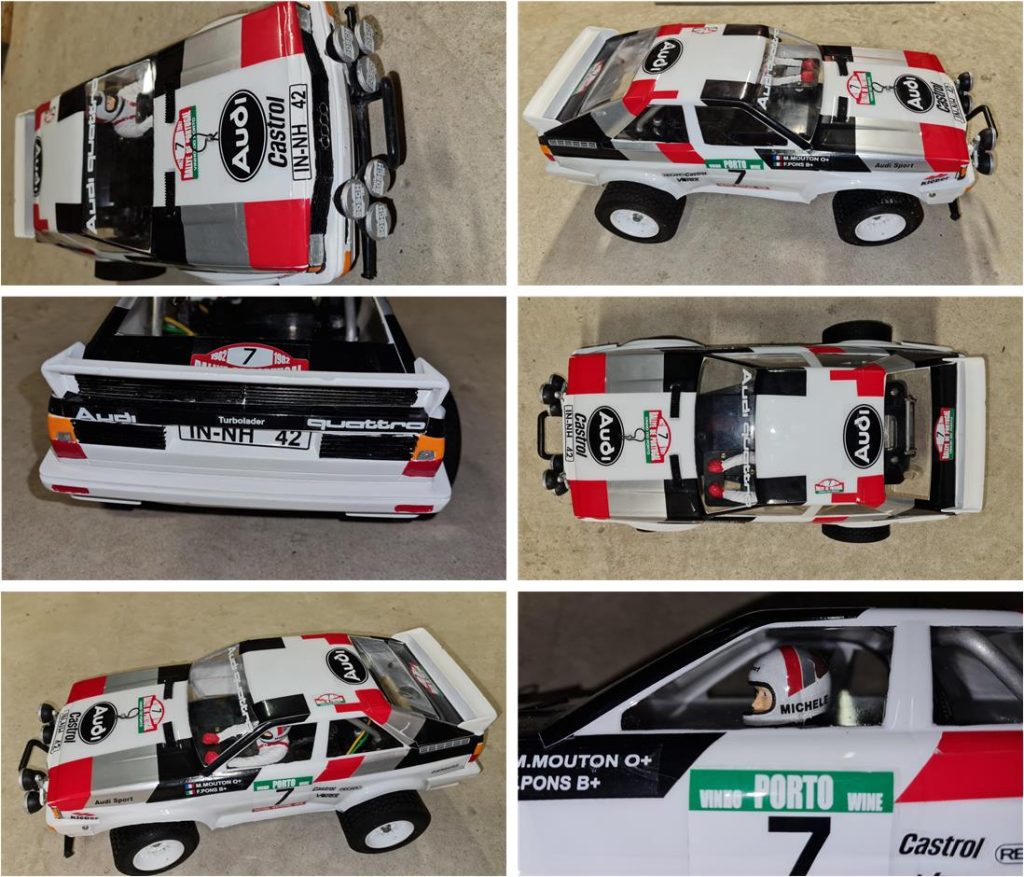
Restored model
Images showing the finished model.
Tamiya, original figure, box art, guide book and catalogue are of TAMIYA INC, which does not endose or sponsor www.tamiyaclassic.com. Any brands, logos and trademarks represented on this website are the copyright of their respective owners.