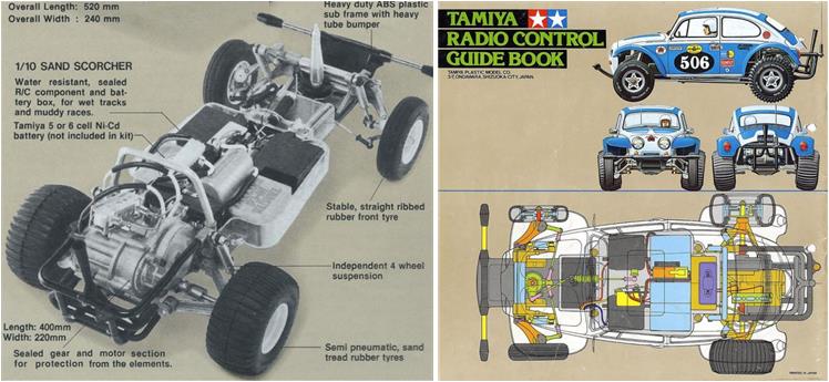
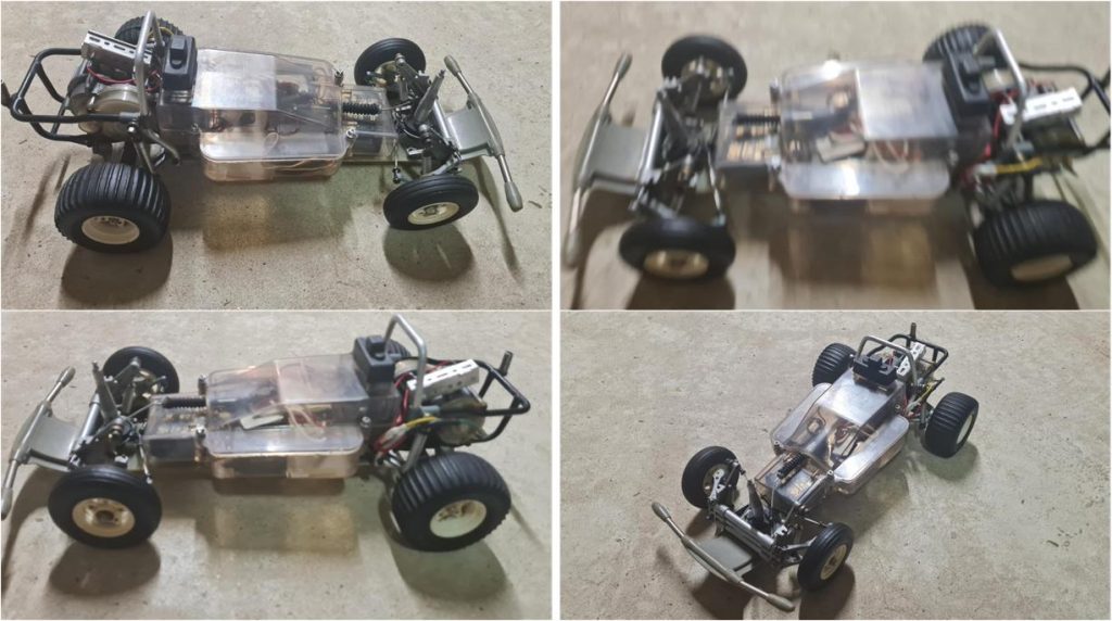
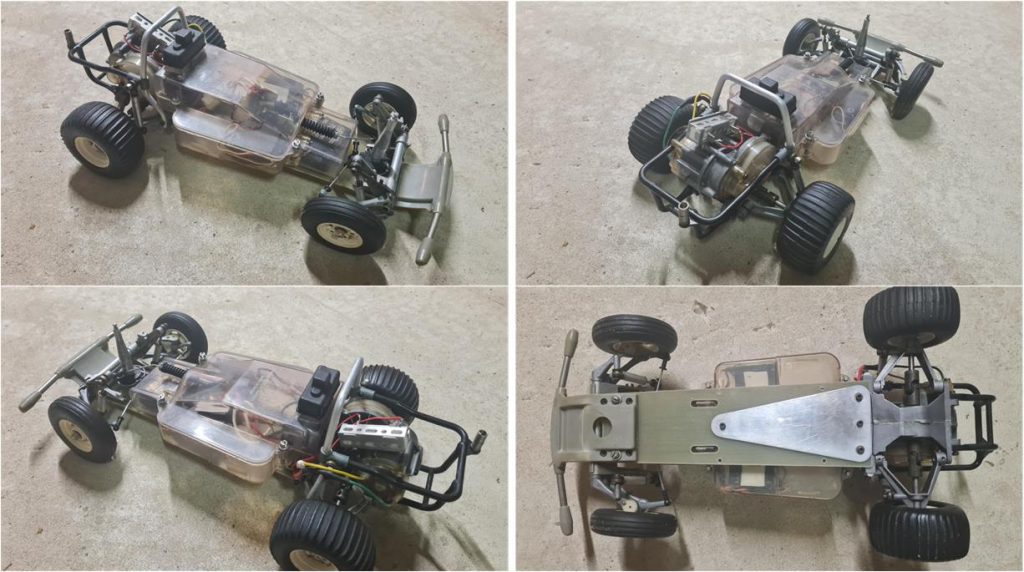
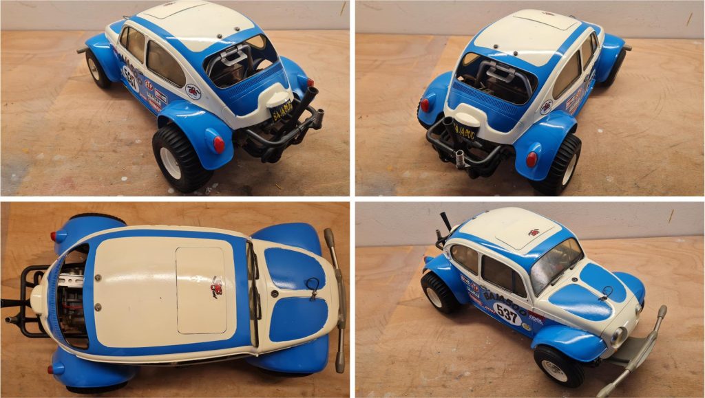
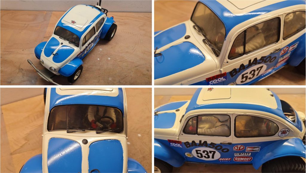
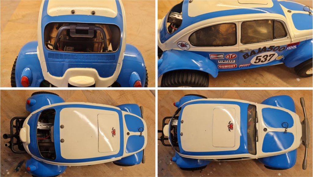
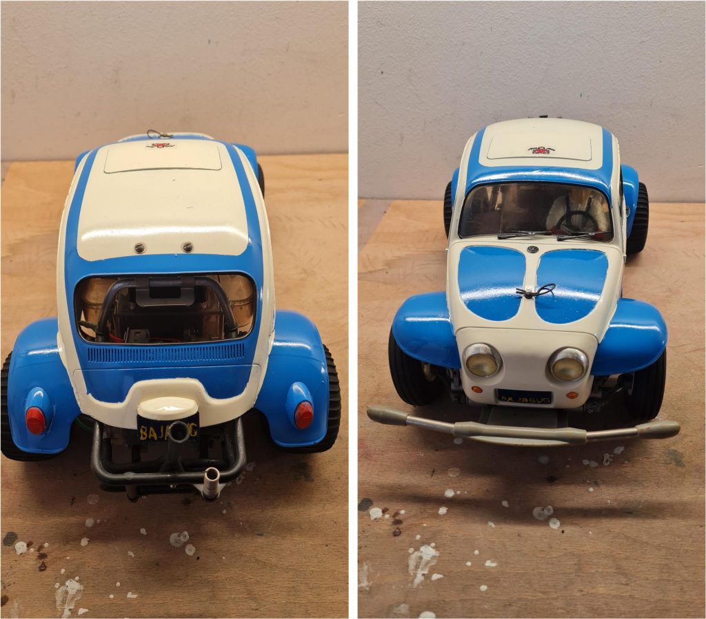
Tamiya Sand Scorcher, item number 58016, released in 1979 and available on the market until 1984. Body made of white styrene. SRB chassis.
This model replicates the Volkswagen Beetle. Tamiya invested significant resources to release this model, which is a 1/10 scale reproduction of the real vehicle. Tamiya reproduced not only the body, but also the mechanics of the model, inspired by the full-scale 1/1 car; the front and rear suspension systems of the Volkswagen Beetle were faithfully replicated with metal parts. In the late 1970s Tamiya catalog, there is a version of the Beetle with a white and blue body (see image below right), which was later adopted as the official livery of the reissue, item number 58452. Tamiya published several advertisements in industry magazines featuring a red and yellow livery. Both versions are iconic, but for this restoration, the catalog livery was chosen, using racing white (Tamiya code TS7) and French blue (Tamiya code TS10).
Analysis of the model to be restored
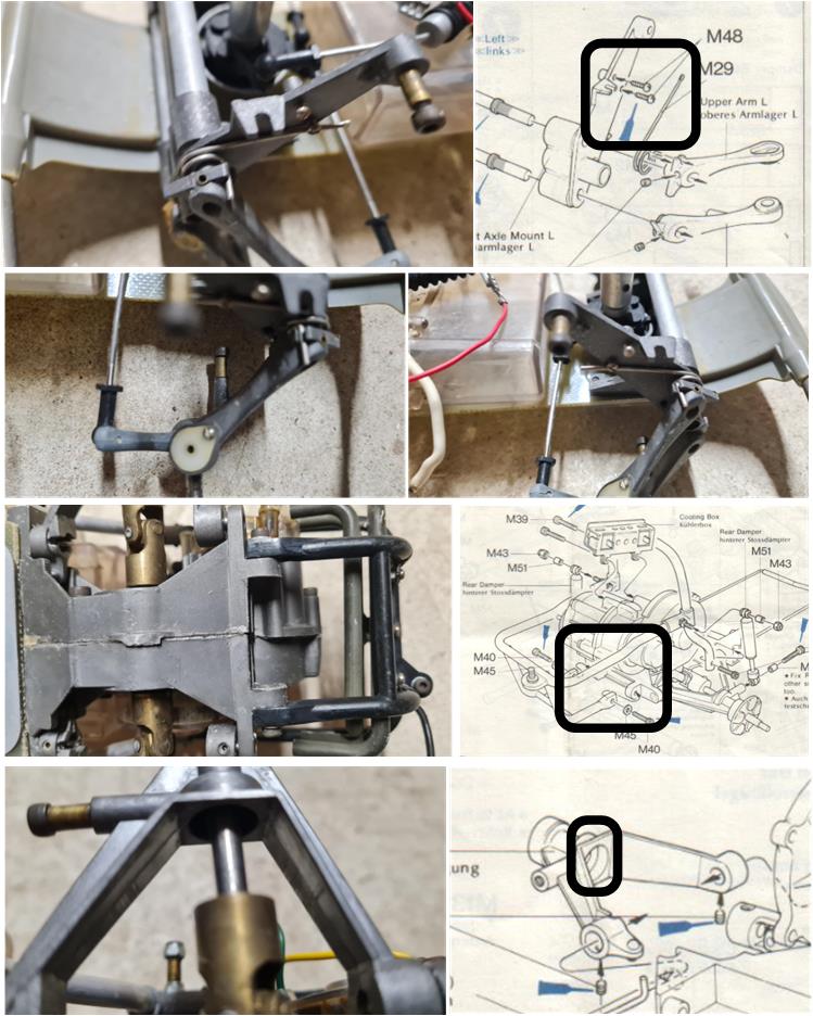
When discussing the SRB chassis, it is essential to determine whether it is a Mk1 version (the first released on the market) or a Mk2 version. Therefore, it is always necessary to analyze all the photos in the online listing to understand what is being purchased. Guide to identifying Mk1 and Mk2 parts. The analysis must be very detailed because Tamiya introduced the Mk2 model updates gradually: some models left the factory with a mix of Mk1 and Mk2 parts. Naturally, this situation—resembling a fruit salad of mixed solutions—worsened over time, as Mk1 model owners repaired damage using parts from the newer Mk2 version. In this lot, several parts are clearly from the Mk1 model:
– the two front suspension towers (images in the first row) equipped with two screws to lock the suspension springs, – the two plus two thin front suspension arms (images in the second row), – the gearbox housing (images in the third row) featuring a recess in the rear section and – the two lower rear suspension arms with a circular internal recess.
The rear box with the suspension therefore appears to be entirely in the Mk1 version.
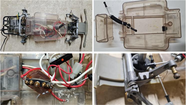
Further chassis analysis reveals another typical feature of the Mk1 model: the electronics box is made of lighter transparent plastic (image, first row on the right). The transparent plastic box that houses the electronics is complete with the lid, lower tray and front shell for the receiver. All these parts are Mk1 version. Additional chassis inspection highlights some areas that require closer attention during restoration: the electronics are present, but the electric resistor and its holder are missing (image, first row on the left). It will be necessary to search for this part among the available spares on the shelves, as it is currently (2025) an extremely rare replacement on the market. The lower arm of the front left swinging suspension shows sealant holding the axle to the suspension pin (image, second row on the right). This part will be carefully examined during chassis disassembly to determine whether it can be salvaged or needs to be replaced.
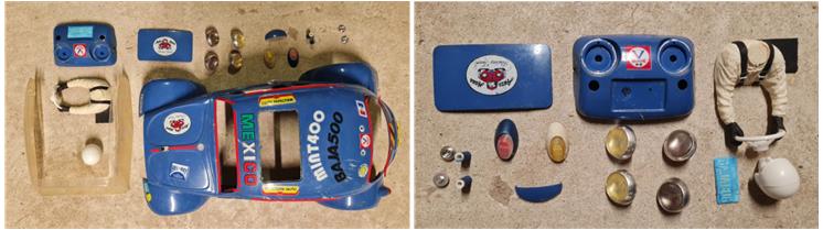
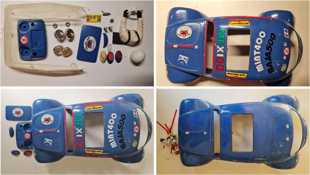
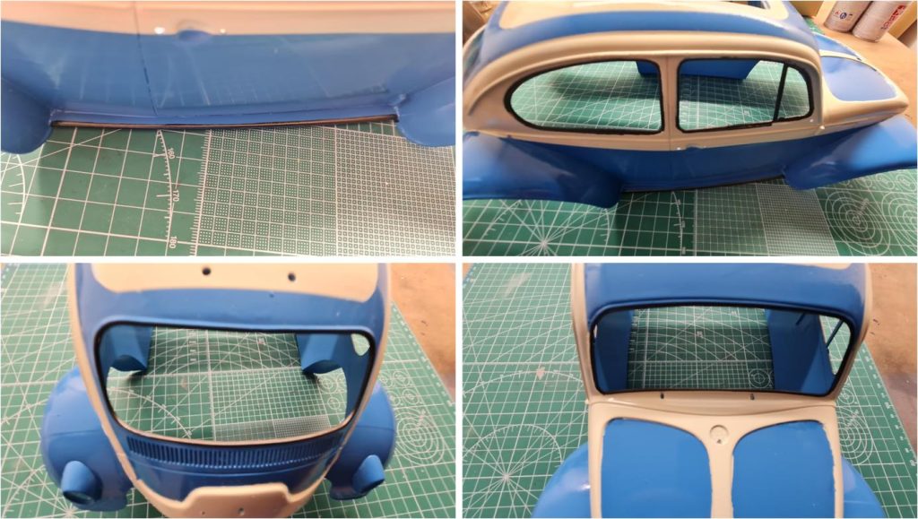
Further chassis analysis reveals features typical of the Mk2 model: the front bumper is gray (image, second row on the right), whereas in the Mk1 version it is black. In fact, few black bumpers have survived over time, as this is the first part to be damaged in the event of a frontal impact and is frequently replaced. Therefore, when the black part breaks, it is often replaced with a gray one, even on Mk1 chassis. The gray bumper does not affect the final result. The body is almost completely disassembled into several parts. Present are the windshield and side windows, the driver figure complete with head and helmet, the front section with the typical indicators of model 58016, the opening roof hatch, rear lights, rear license plate lights and pins for the body locking system. Missing are the two transparent plastic pieces that simulate the front indicator lights, which today (2025) can be sourced from the re-release set with code 19115269; however, the two chrome parts on which the orange indicators are mounted are present.
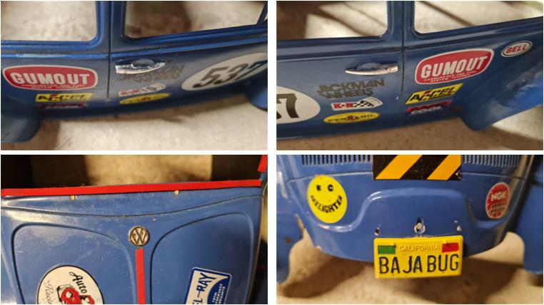
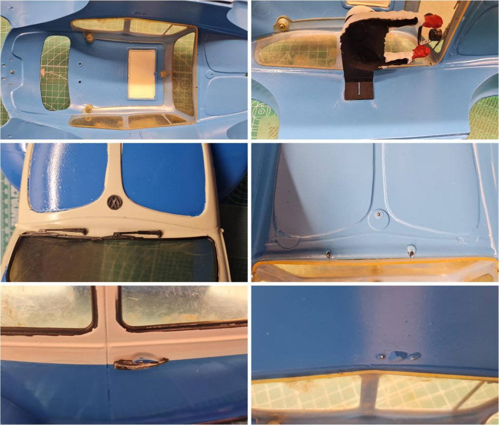
All the parts that are often damaged or missing are present, such as the right door handle (image, first row on the left), left door handle (image, second row on the right), Volkswagen emblem on the hood (image, second row on the left) and license plates with raised lettering (image, second row on the right for the rear plate). The two side mirrors, right and left, are missing—these parts are rarely found. The analysis confirms that the body is in excellent condition, with a good selection of accessories to enhance the final result. The paintwork is completely non-standard, so it cannot be salvaged.
Chassis Restoration
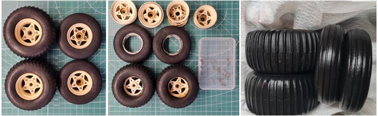
Based on the analysis of the chassis and body parts, it is clear that the front bumper is gray (as in the Mk2 version, instead of black as in the Mk1 version) and the two side mirrors are missing from the body. All other parts in this lot conform to the specifications of the Mk1 model. The goal is to restore this model to factory condition while preserving signs of aging: a conservative restoration. A conservative restoration means that the chassis must be in order with parts as faithful as possible to the original Mk1 factory specifications (only the bumper is Mk2) and the bodywork must have the correct paint scheme (only the two side mirrors are missing). When starting a restoration, the rubber parts of these models are the most delicate. Most components are made of metal or FRP (Fiber Reinforced Polymer), which are less affected by the passage of time compared to rubber parts. Since rubber restoration takes about three weeks, to avoid delays in the overall process, it’s best to begin with these components. This section explains how to rejuvenate rubber parts that have deteriorated over time. The wheel tires must be separated from the plastic rims. For SRB chassis Sand Scorcher models, the central part of the rear rim is embedded inside the tire. Removing it could damage the rubber itself; if the rubber is considered too fragile, it is recommended not to remove the insert from the rear tire, as glycerin treatment does not negatively affect the plastic rim (center image shows the rear wheels with the central rim insert left in place).
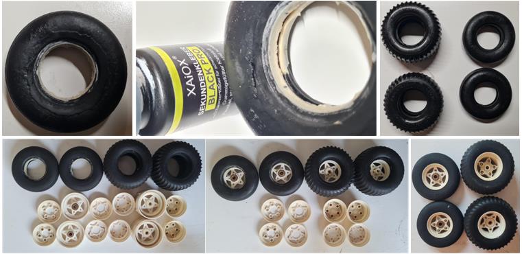
Upon inspecting the tires, it became clear that the front tire sidewalls show a few small cuts. The tread is in excellent condition, but the sidewall has short and minor cuts; it is reasonable to consider restoring the rubber through repair. Before proceeding with glycerin rejuvenation, seal these cuts using black cyanoacrylate glue applied inside the damaged areas (see center image in the first row). In this case, the tires are soft enough to allow removal of the central insert from the rear wheels (image on the right in the first row). While the tires are being treated with glycerin, the rims are cleaned with hot water and degreasing dish soap, then wiped with a cloth soaked in alcohol. The Tamiya instruction manual does not recommend painting the rims, so they are treated not for painting preparation but to restore their original shine without removing the color altered by years of sun exposure. Once both treatments—rubber and plastic—are completed, the two front wheels and two rear wheels can be assembled (images in the last row).
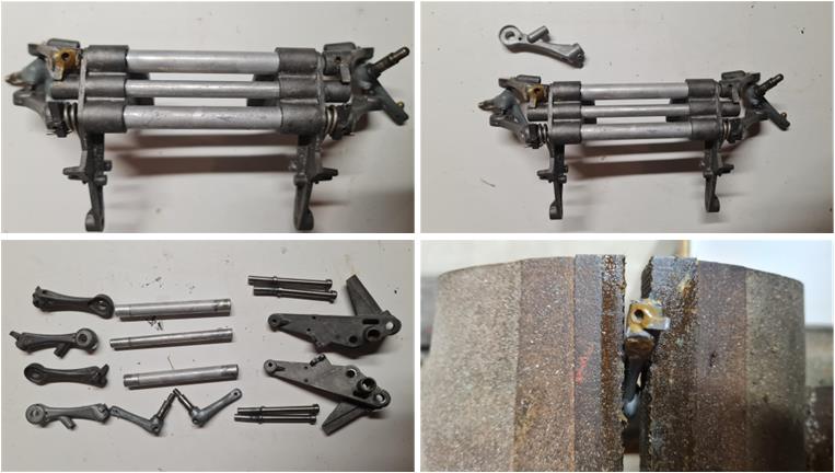
After beginning the regeneration of the four tires, it’s time to focus on the chassis: disassembling it piece by piece to check for hidden damage, incorrect hardware and missing or non-compliant parts. The front chassis, which houses the double wishbone suspension system, shows a defect that was already visible during the photo-based analysis of the listing: the lower left suspension arm is damaged at the grub screw that secures it to the pin (image, second row on the right). The damage can be repaired by enlarging the hole from 3 mm to 4 mm and threading the new hole in the arm to allow installation of a larger grub screw. In this case, a spare lower arm is available (image, first row on the right), Mk1 version and intact. Replacing the part is preferable to repairing it. No other issues were found in the front section: all components are compliant for a Mk1 chassis restoration.
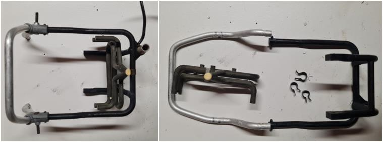
The roll bar protecting the rear gearbox housing is made of one plastic part and one metal part. Attached to this roll bar is the mock exhaust of the combustion engine. The two components forming the roll bar are intact, but part of the exhaust is missing; the final trumpet section is no longer assembled with the other parts (image on the left). The three metal clamps that secure the exhaust system to the roll bar are present (image on the right).
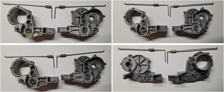
The gearbox housing is in excellent condition. The state of the retaining ring suggests that the model has seen little use or that the ring was replaced recently, as it shows no signs of wear. The lower suspension arms are Mk1 version and are in perfect condition. The axle joints are of the lighter-colored type, typical of Mk2 models. Since this part tends to wear out over time, it is likely that they were replaced.
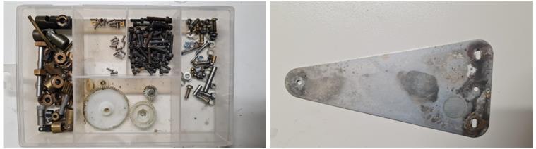
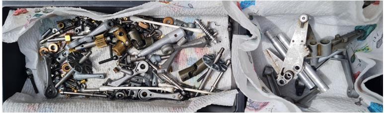
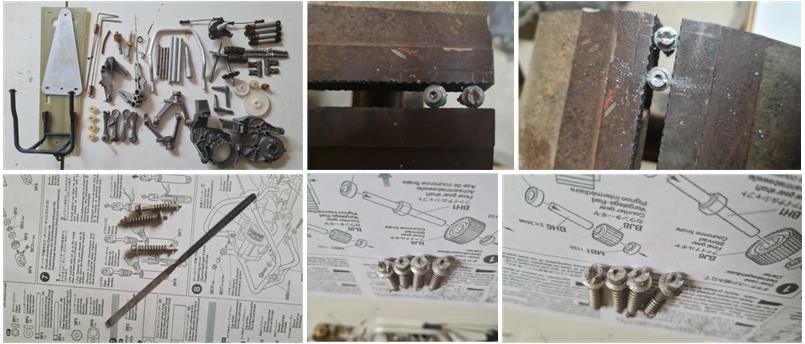
Once the chassis has been fully disassembled, separate the hard plastic parts from the transparent plastic parts, the metal components and the FRP parts. The small metal hardware (image on the left) undergoes a restoration treatment using a diesel bath: they are immersed for one week in a container filled with diesel fuel. Diesel chemically breaks down oxidation, rust and grease. Larger metal parts that cannot be submerged in diesel—such as the lower chassis reinforcement (image on the right)—are cleaned with WD40, which dissolves oxidation, grease and rust.
The WD40 treatment involves thoroughly soaking the surface to be cleaned with WD40, followed by scrubbing with the bristles of a hard-bristle toothbrush. WD40 chemically breaks down oxidation, dirt and grease, while the toothbrush mechanically removes these residues. The combined action of WD40 and the brush restores metal parts affected by years of exposure to air and use. In the four images below, various stages of the process are shown: the first image at the top left displays the parts just disassembled and the final image at the bottom right shows the parts after treatment.
After disassembling the chassis and body, inspect the hardware to ensure it complies with the factory specifications for this model: all screws (ranging from 2 to 4 mm in diameter and various lengths) must have slotted heads. Any Phillips-head screws should be replaced with slotted ones to restore the chassis to a configuration as close as possible to the Mk1 version. Over time, some screws may have been replaced during routine maintenance with newer Phillips-head types or non-Tamiya components. The hardware and small metal parts are treated in diesel (see the treated parts in the image below). Diesel chemically breaks down oxidation, rust and grease, leaving a thin protective film on the surface of the treated metal that helps prevent future corrosion.
Once the metal parts have been treated, attention can shift to the hard plastic components—specifically, the transparent plastic electronics box. After removing the adhesive residue with a cloth soaked in alcohol, wash the parts with hot water and degreasing dish soap. In the image on the left, the parts are shown before treatment with alcohol and soap; in the center and right images, the parts appear after cleaning. This process restores the components to a condition similar to when they were new. The plastic shows some cracks, which do not compromise its functionality. After all these years, the material has lost some of its elasticity, resulting in minor fractures. If care is taken during installation, these cracks and breaks will not spread.
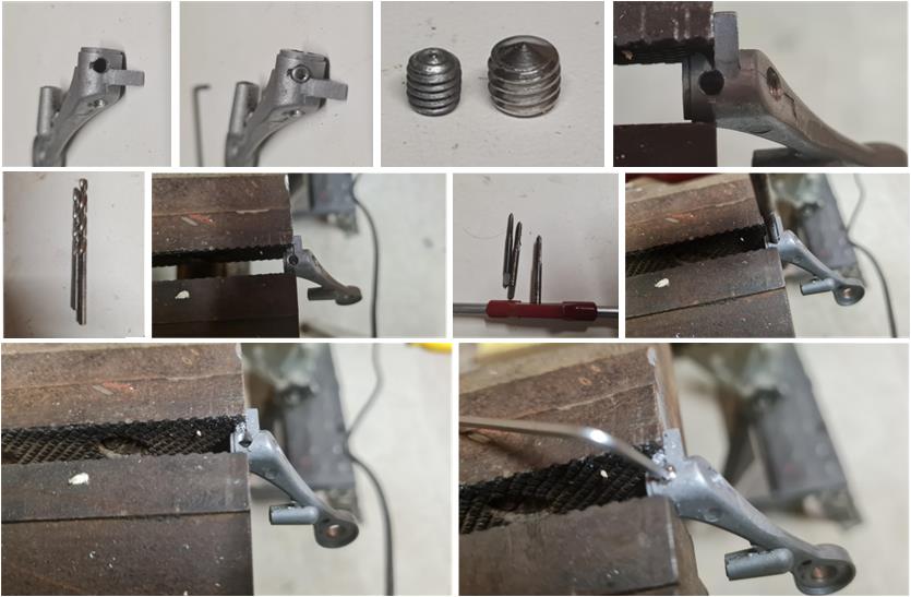
Before assembling the chassis, it’s necessary to revisit the lower left front suspension arm on the model, which was clearly damaged—the grub screw was held in place only by threadlocker, which does not grip the metal. The replacement part found on the shelves, initially selected for the restoration, turned out to be unsuitable. Although it appeared intact, the center-left image reveals a missing fragment around the thread, resulting in an irregular, non-circular hole: the grub screw cannot grip the metal properly. Thus, the replacement part suffers from the same defect as the original. The only viable solution is to proceed with a repair and replace the 3 mm grub screw (shown on the left in the second-to-last image of the first row) with a 4 mm one (shown on the right in the same row). Sequence of operations to repair the lower suspension arm:
– Secure the damaged part in a vise (image on the right in the first row) – Enlarge the hole using a 3 mm metal drill bit (left image in the second row) to completely remove the original thread – Further enlarge the hole with a 3.5 mm metal drill bit (right image in the second row) to prepare it for threading – Tap the hole using a set of 4 mm thread taps (right images in the second row; typically, three taps are used to gradually form the thread: one to start, one to deepen and one to finish) – Install the new 4 mm grub screw (images in the last row)
This repair ensures a secure and functional connection, restoring the integrity of the suspension arm for proper assembly.
Upon inspecting the metal parts, it is clear that 3 out of the 4 pins securing the upper shell of the electronics box to the lower shell are missing. Replacement pins from the re-release are available, but they differ slightly—they lack the slotted head (see center image in the first row, with the new version on the left and the original on the right). The pins are made of aluminum, making it easy to create a slot using a metal scribe (image on the left in the second row). The initial cut does not perfectly replicate the slot found on Mk1 and Mk2 series pins, so further shaping is done using a flat metal file to recreate the exact original profile. The slot edges must be rounded and widened. In the final image, the modified pins are shown after filing, successfully reproducing the original Mk1-style appearance.
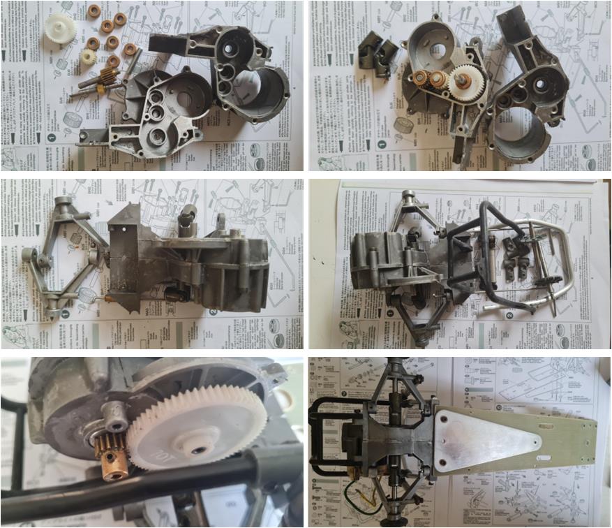
Proceeding with the next steps, the rear gearbox—composed of two shells—is assembled. The rear roll bar is installed within this assembly to protect the motor and the rear suspension, which is mounted directly to the roll bar. Once this unit is complete, the chassis begins to take shape by connecting it to the central FRP frame and the metal triangle. The original lot included bronze-colored dogbone joints, typical of Mk2 models. Fortunately, two olive-colored joints—matching the Mk1 specification—were found among unused parts from previous restorations. These were installed to ensure the build remains consistent with the Mk1 configuration, with the only exception being the gray front bumper instead of the original black.
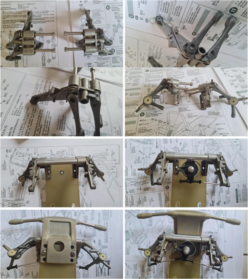
Assemble the front section composed of the double wishbone suspension system with its two towers (images in the first two rows), the steering mechanism (images in the third row) and the gray bumper (the only part in Mk2 version, shown in the last row). This entire assembly is mounted onto the FRP plate and at this stage, the chassis has fully taken shape.
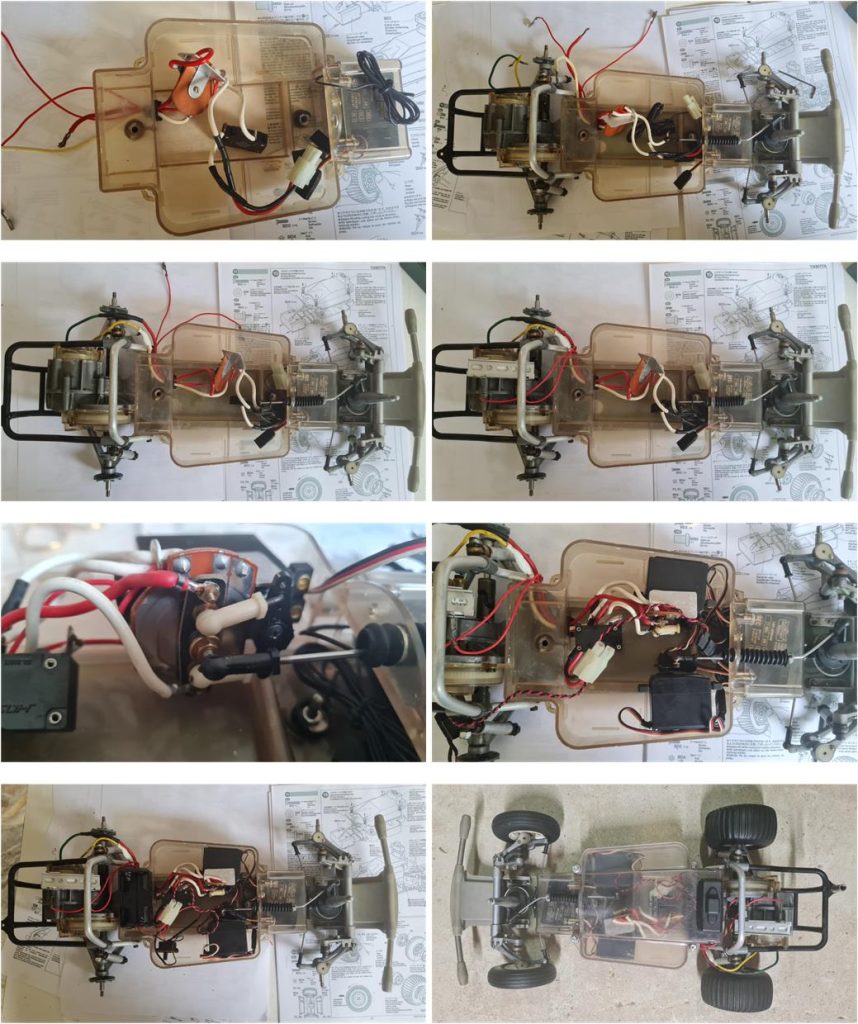
Before installing the electronics box onto the chassis, route the electrical connection cables through the lower shell (image on the left in the first row). In the original lot, the mechanical motor speed control system was incomplete. Fortunately, an SRB chassis resistor was found among unused parts from previous restorations: the mechanical speed control is now complete, including the safety switch, in accordance with Mk1 factory specifications. Once the wiring has been passed through the cable guides, the lower shell can be mounted onto the FRP chassis and the wiring completed toward the motor and resistor (image on the right in the first row and in the second row). To finish the electronics installation, secure the two servos with double-sided tape and mechanically connect the steering rods (image on the left in the last row). Finally, install the upper shell and the four previously restored wheels (image on the right in the last row).
Now the chassis is ready to be joined with the body.
Body Restoration
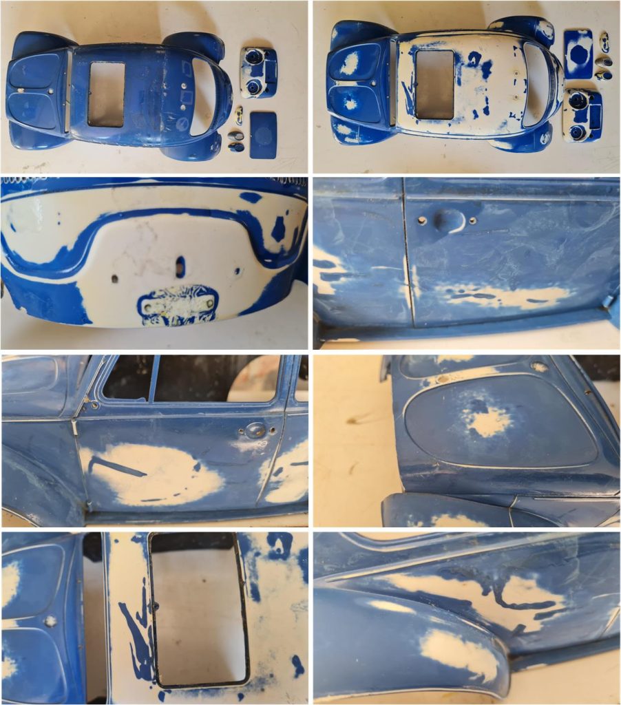
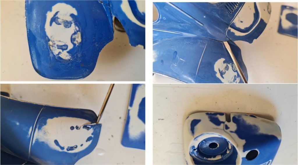
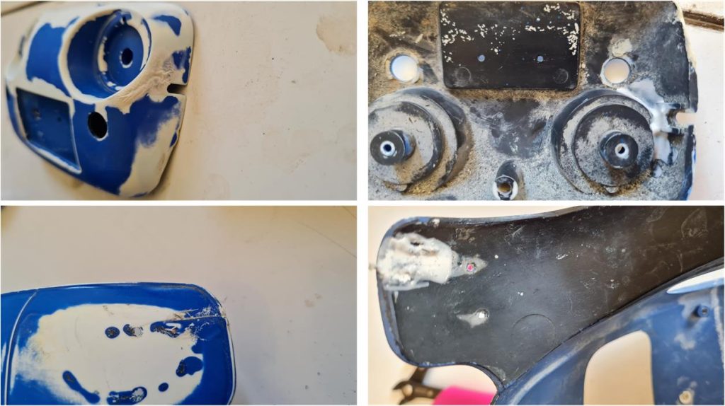
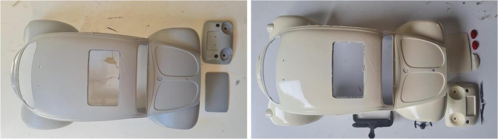
The body requires repairs in some areas and must be painted with the correct livery. First, separate all small parts from the main body: door handles, U-shaped front and side windows, driver figure, front section with lights and indicators, front headlights, license plate light guards, etc. (parts shown in the first row image). These parts are usually glued with cyanoacrylate adhesive, so force must be applied carefully to pry them off. Proceed gently and patiently to avoid breakage, as the glue has crystallized over time and tends to snap under stress. Immerse the body and all styrene parts in alcohol to remove all stickers and adhesive residue (image on the right in the second row).
A small piece of the driver figure’s L-shaped plate and glue residue remained attached to the inner part of the body where the driver is positioned (left image). Work the surface with a medium-grit file to remove all plastic and glue remnants (center image). Be careful with the tab that serves as a guide for installing the driver figure—this tab must not be filed (left image).
Alternate baths in 99% pure alcohol with mechanical treatments by wiping the surfaces with kitchen paper towels. This process removes most of the paint and glue. Continue this dual treatment as long as paint is still being removed by the paper towel. When the mechanical action of the towel and the chemical action of the alcohol no longer have any effect, work the surfaces with wet 3000-grit sandpaper following these simple guide.
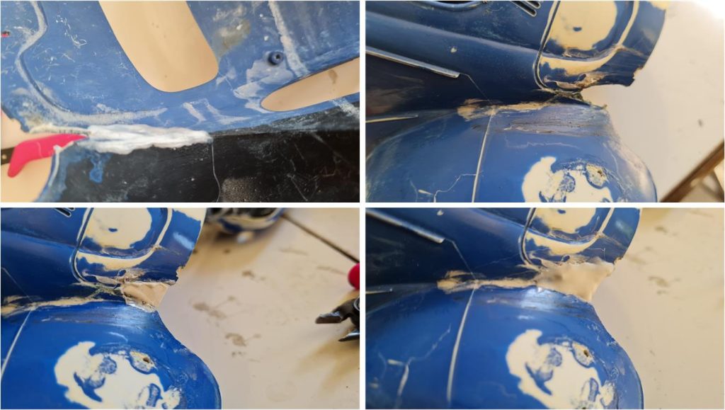
There are several cracks and fractures both on the front part of the body, which is the nose (image on the right in the second row) and on the main body shell (images in the second and first rows). To highlight the fractures, the tip of a flat screwdriver was inserted into the crack: by gently prying, the two edges can be seen separating (image on the left in the second row).
To repair the parts, it is necessary to apply a solution of acetone and ABS along the fractures. Follow these steps: first, moisten the edges of the fractures with pure acetone to prepare the surfaces. Then, using a brush, apply the more fluid solution along the fracture line; the liquid penetrates into the crack. It is better to apply the material generously (image on the right in the second row) to ensure deeper penetration of the solution. The excess solution will be removed later (wait at least 24 hours to allow the solution to bond the parts) by sanding the repaired surfaces with 1000- and 2000-grit sandpaper.
The images show the acetone and ABS solution applied to the fractures throughout the body shell.
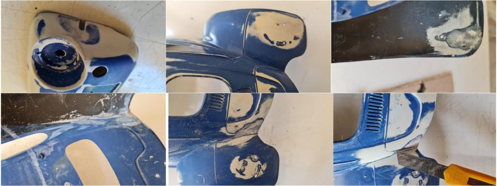
Work the freshly treated surfaces using wet sandpaper starting with 1000 grit, followed by 1500 grit and finally 2000 grit. If there are pronounced lines or moldings that need to be replicated, use the tip of a utility knife with a wavy motion to scrape away excess material and carve out the lines (see image on the right in the second row).
Apply several coats of grey primer to prepare the surface for the first layer of TS7 Racing White. Then apply multiple coats of TS7 Racing White until the surfaces appear smooth and glossy.
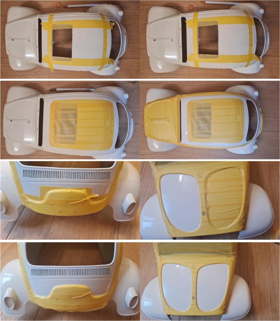
Before applying the TS10 French Blue color, proceed with masking the body. The areas that will remain Racing White must be covered with masking tape or painter’s tape. The most complex masking task is the upper section, as the roof requires a white rectangle with rounded corners. To mask the roof, follow these steps: outline the sides of the rectangle (image on the left in the first row) using masking tape, define the four curved corners with a pencil using a 2-cent coin or a washer of the correct diameter as a guide (image on the right in the first row), cut the curves with a scalpel and complete the masking of the central roof area (image on the left in the second row). The roof is the most demanding part of the masking process, but not the only one: portions of the side panels, the two air scoops on the front hood and part of the rear section also need masking. Mask all other areas of the body that must remain Racing White (part of the right side panel, part of the left side panel, the nose and the rear engine bay). Use a scalpel to trim any excess tape (image on the right in the third row, showing the passenger-side hood scoop) and now the body is ready for painting. The images below show the results for both the front section (image on the right in the last row) and the rear section (image on the left in the last row).
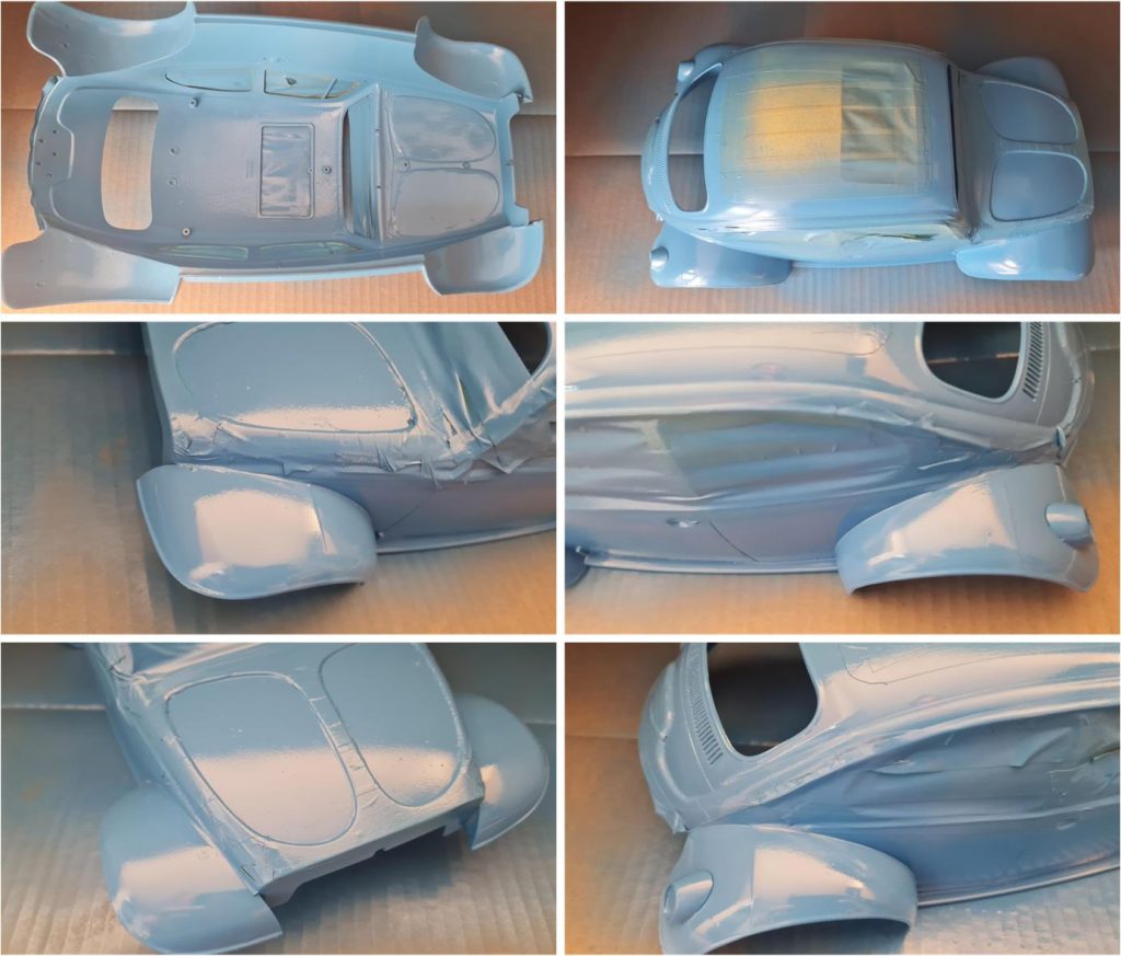
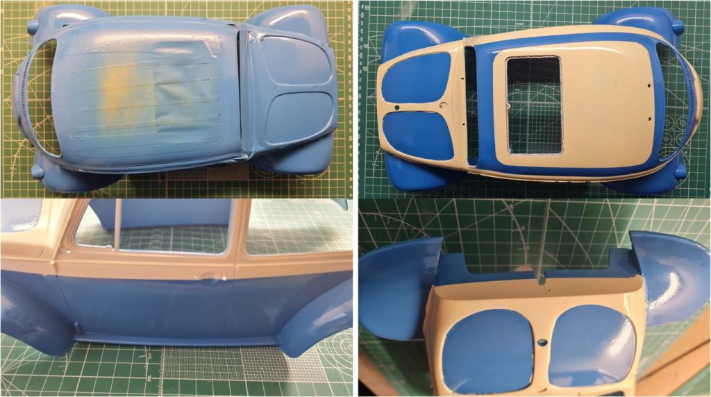
Apply TS10 French Blue starting with light coats, followed by wetter coats. Refer to the guide on how to apply paint to styrene parts. Paint both the outer and inner surfaces. After applying the final coat of French Blue, wait between two and four hours before removing the masking tape. Waiting longer increases the risk of the blue paint chipping or cracking along the masked edges. Waiting less increases the risk of the blue paint peeling off in areas where it hasn’t fully adhered.
After applying the final coat of French Blue, wait between two and four hours before removing the masking tape. Waiting longer increases the risk that the blue paint may chip or crack along the edge of the masked area. Waiting less increases the risk that the blue paint may peel off in areas where it should remain, as it has not yet fully adhered.
Apply XF1 black to the two side sills (image on the left in the first row), to the edges of the four side windows and to the borders of the windshield and rear window. The black trim simulates the rubber gasket for the side windows, rear window and windshield.
Install the windshield and side windows, which are formed as a single U-shaped piece, secured with three slotted-head screws to comply with factory specifications (image on the left in the first row). The license plate light cover is also fixed with a slotted-head screw. Using UV-activated adhesive or sunlight-curing glue, attach:
– the Volkswagen emblem and the two windshield wipers (images in the second row) – the right and left door handles (images in the third row)
Glue the driver figure using either UV-curing adhesive or a drop of cyanoacrylate glue.
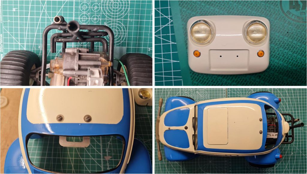
Using the three metal clamps (image on the left in the first row), screw in the slotted-head screws to secure the trumpet-style exhaust to the rear roll bar, protecting the gearbox housing. Attach the two front headlights to the nose using two 2 mm slotted-head screws and glue the two turn signals to the nose (image on the right in the first row). Fasten the clip that locks the body to the rear roll bar with two screws (image on the left in the second row). The body is now ready to be joined with the chassis and a test fit can be performed to verify that everything has been assembled correctly (image on the right in the second row). Now the decals can be applied and the two license plates glued in place with a small drop of cyanoacrylate. The two rearview mirrors are not present; to preserve the spirit of a conservative restoration, the option of installing 3D-printed reproductions was not considered. As of today (2025), original mirrors are unobtainable, although several replicas are available.
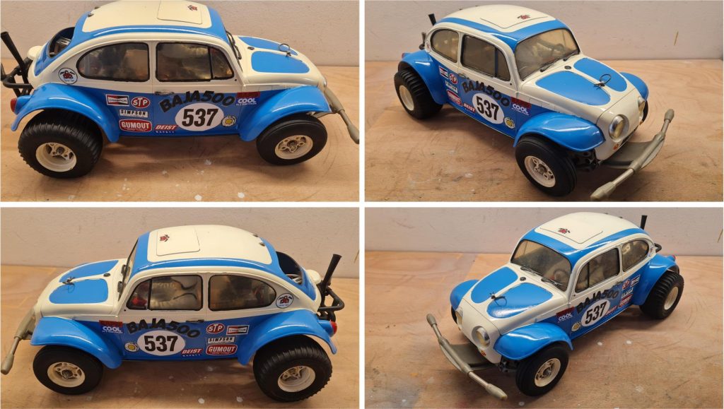
Restored model
Images showing the completed model with body.
Tamiya, original figure, box art, guide book and catalogue are of TAMIYA INC, which does not endose or sponsor www.tamiyaclassic.com. Any brands, logos and trademarks represented on this website are the copyright of their respective owners.