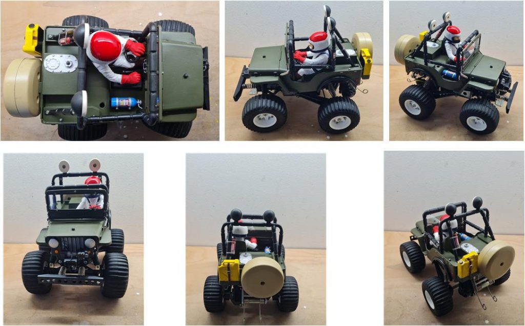
Tamiya Wild Willy, item number 58035, released for sale in 1982 and available on the market until 1987 in two versions: the early models were the short wheelbase (SWB) version, which later evolved into the long wheelbase (LWB) version during mid-production. Body made of Styrene. Wild Willy chassis and the model in question is the SWB short wheelbase version.
Analysis of the model to be restored
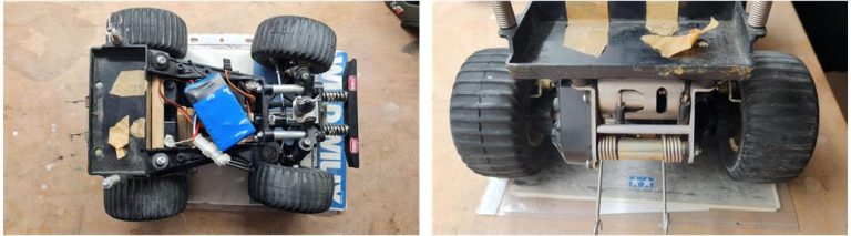
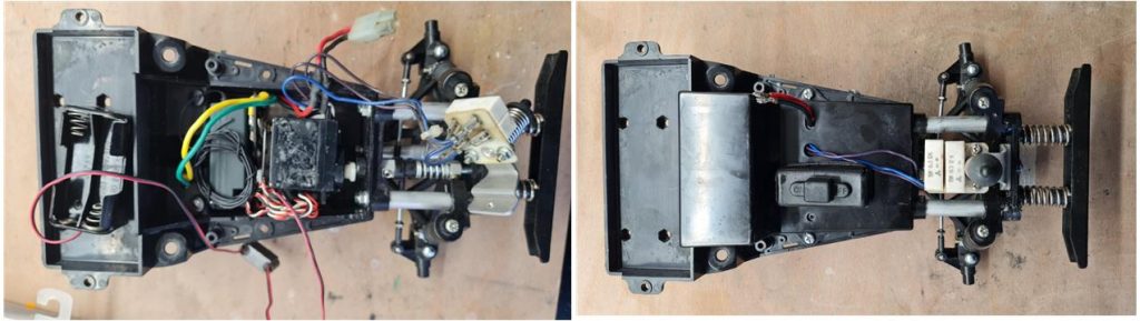
The model to be restored has undergone several modifications and has evidently been heavily used. An initial analysis of the chassis photo (image on the left) reveals that the lower electronics housing has been modified using balsa wood to accommodate the receiver, steering servo motor and auxiliary battery pack for electronics. The upper electronics housing is missing and some parts have been repaired using masking tape (image on the right).
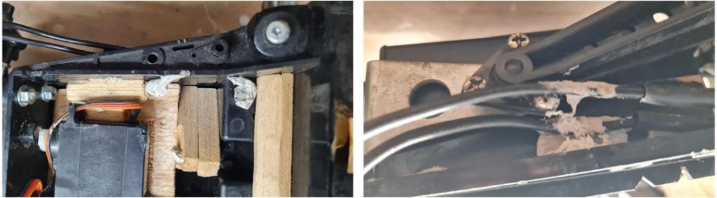
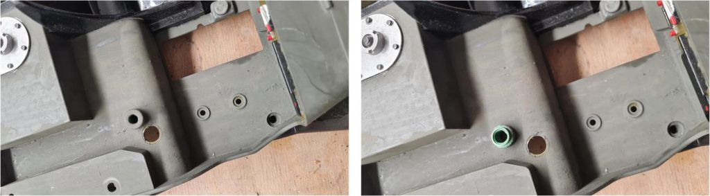
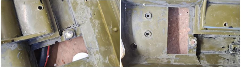
Gray adhesive paste was used to secure the additional wooden parts (image on the left) and the battery and motor cables (image on the right).
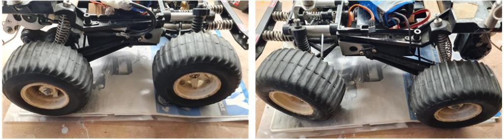
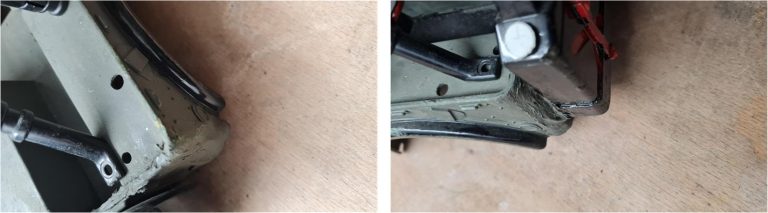
The rims and tires appear to be in good condition, with no damage or tears on the sidewalls and tread. The images show an L-shaped metal insert supporting the rear suspension arm, which is characteristic of the short wheelbase version with a circular hole.
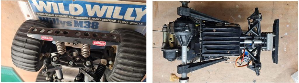
The front bumper (image on the left), which is the most stressed part in the event of frontal impacts, is in excellent condition. The lower shell (image on the right) shows no significant scratches or breaks. These two pieces appear to have not undergone too severe a treatment; however, the same conclusion cannot be reached when observing the body.
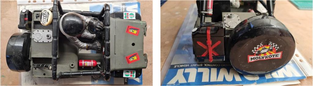
The body is certainly in much worse condition compared to the chassis. It has suffered from intensive use and some parts have been repaired after the body likely broke due to impacts. The upper part and the rear section of the body appear to be in nearly good condition and complete in their components, except for a noticeable issue with the front part of the hood.
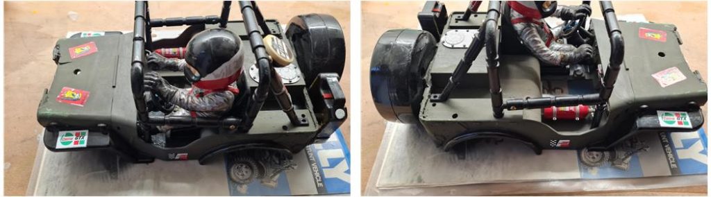
From the analysis of the right and left sides, it is evident that the right spotlight of the roll bar is missing, while the little driver figure and the fire extinguisher are present and intact.
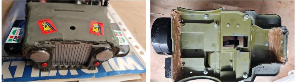
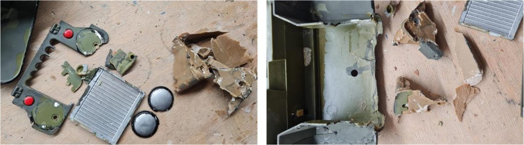
The front and the view of the underside of the body highlight that the model has experienced several accidents along the way: the front (image on the left) is the part that has suffered the most damage, as the winch is missing (it is included in the received parts but is broken in several places) and the grille is completely shattered. From the image of the underside (image on the right), it can be seen that resin has been used to repair and reinforce the front and rear sections, which are prone to impacts.
Chassis Restoration
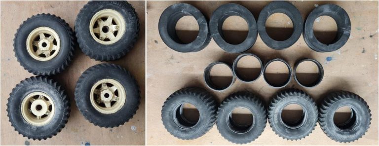
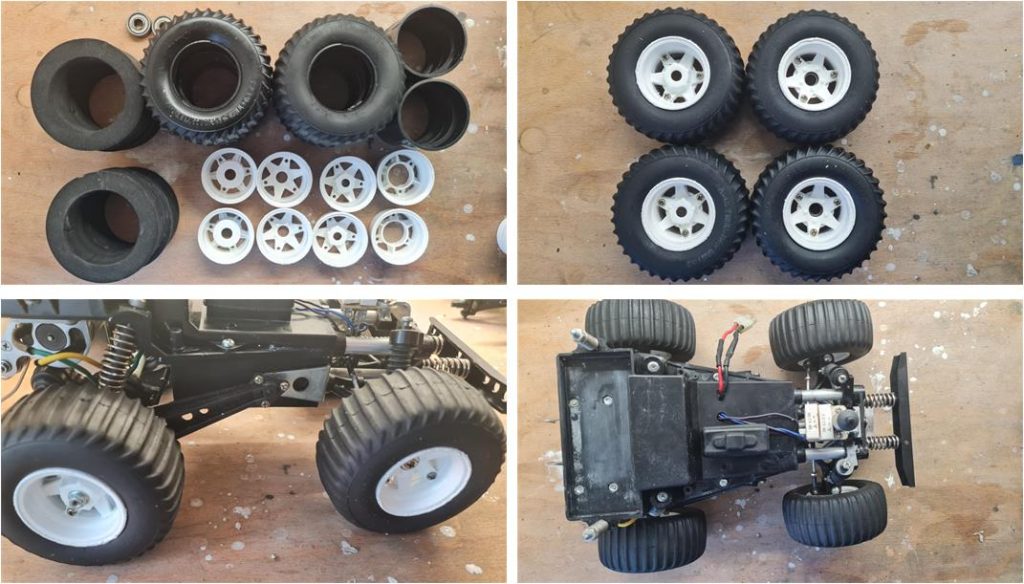
The first step is to remove the wheels and separate the rims from the tires. Inside all four tires, there is a dense foam rubber insert and a plastic ring. These two inserts provide rigidity to the sidewalls of the tire tread, preventing them from being excessively affected by the model’s weight. After all these years, they have been the crucial components that preserved the tires from becoming misshapen. The four tires have lost elasticity and show signs of aging, yet they have no cuts or holes and the tread remains in good condition. To remove years of dust and grease from the tires, wash them with warm—lukewarm—water, using a toothbrush with soft bristles and a bit of dishwashing detergent to degrease. The soap emulsifies the grease, making it easy to rinse away during washing. Without soap, the grease would simply be shifted from one area of the tire to another. At this stage, it becomes even more apparent that the tires have aged over time. To restore them, it’s best to treat them with glycerin. Follow these steps for regeneration using pure 99% glycerin:
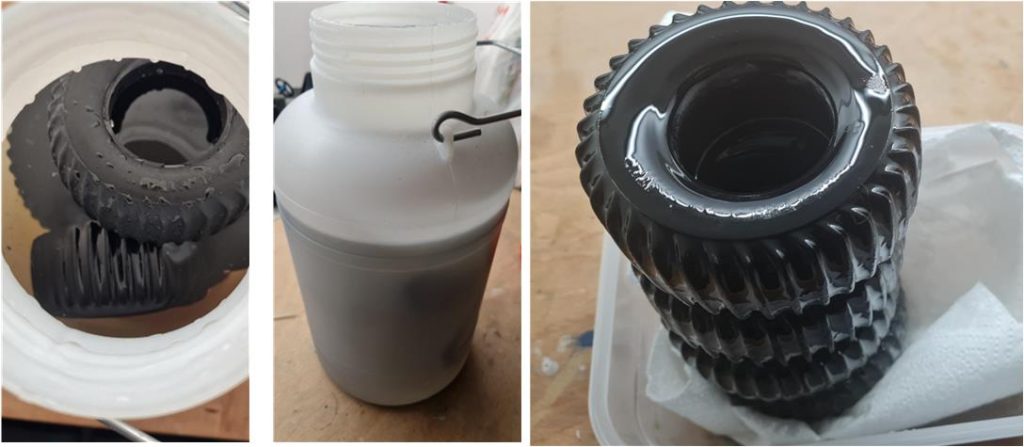
– Immerse the tires in glycerin for at least a week; extend this period by a few more days if the rubber is particularly inelastic. – After the glycerin soak, let the tires rest on a kitchen paper towel for a week. During this phase, the rubber will expel excess glycerin, so replace the kitchen paper towel at least once a day. – At the end of the treatment, the tires will have regained their original appearance. Over the next 5 or 6 days, wipe the tires daily with a kitchen paper towel to remove the remaining residue.
Use a container with a screw-on lid and seal to prevent moisture (and therefore water) from altering the regenerative properties of glycerin. The container’s opening is sufficiently wide to easily accommodate the tires of larger models as well. Inside, there are approximately 5 liters of glycerin, which can be reused multiple times.
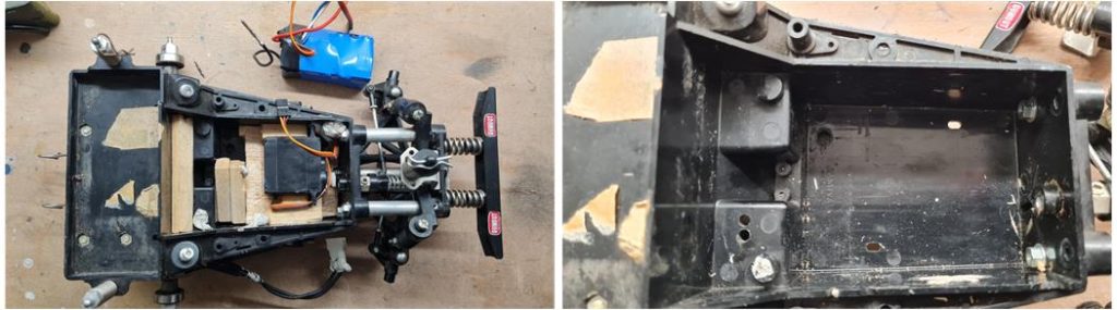
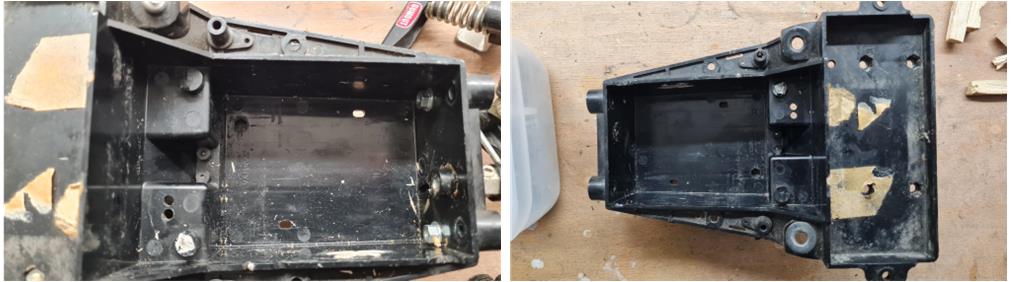
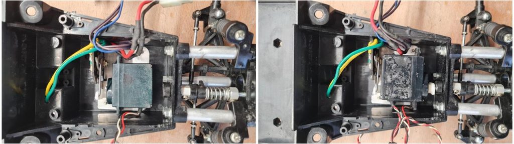
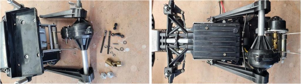
A restoration is truly complete only when every part of the model is cleaned, inspected and either repaired or replaced if damaged. In the images below, you can see the chassis ready to begin the restoration: in the image on the left, the lower chassis shell is devoid of the balsa inserts that the previous owner had used to install electronics.
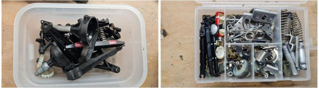
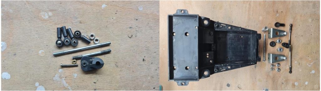
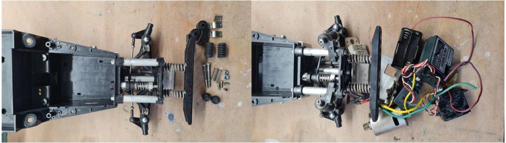
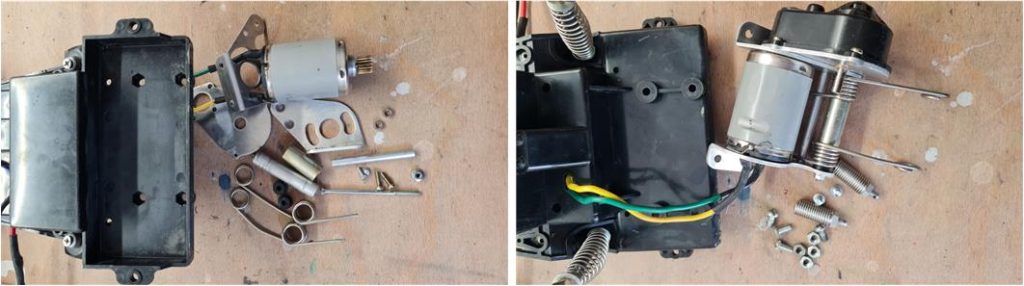
After disassembling the various components, it is best to sort them by type; plastic and metal parts will undergo different cleaning processes. During the disassembly of the chassis, there was only one surprise: the metal chassis designed to house the steering servo motor and the mechanical speed controller in tandem is missing. It is always a good practice to save and catalog leftover parts from a restoration—thankfully, in this case, the metal plate is among the spare parts. In the image on the left, the plastic components are visible and on the right, the metal parts can be seen.
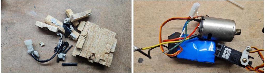
In the image on the left, all the components that are not part of the original setup have been gathered: balsa wood, connectors different from the Tamiya ones and a substantial amount of gray adhesive paste that the previous owner had used to secure cables and the balsa wood. Of all these parts, only the motor and the steering servo motor will be used to complete the restoration.
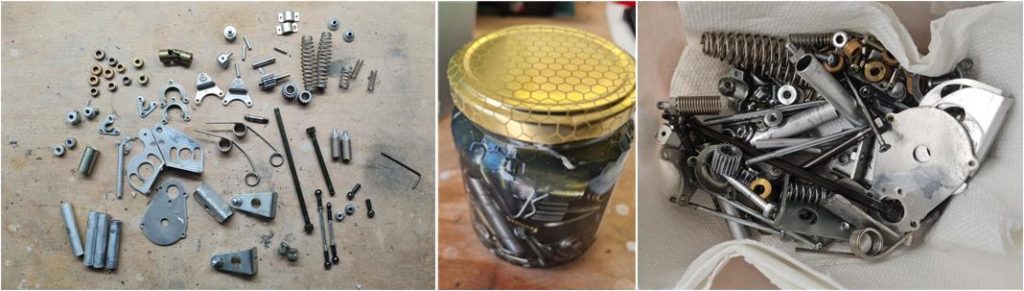
Treat the metal parts with diesel fuel. Using a glass jar with a sealed lid, immerse all the components in the diesel fuel for at least a week. Diesel chemically reacts with grease, oxidation and rust, restoring the parts to almost new condition. After treating the parts with diesel, leave them in the sun for a few days so that the excess diesel evaporates. The treated parts will then be coated with a thin film of diesel, which protects them from oxidation. Following this treatment, the parts regain their shine, with only the wear-related scratches remaining.
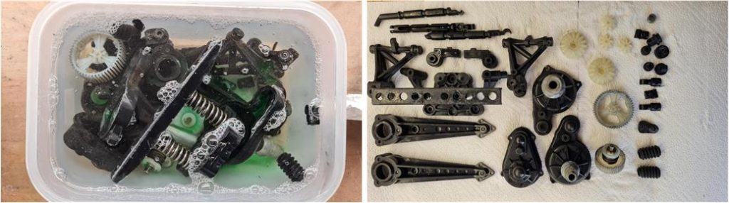
Treat the plastic parts with water and dish soap, leaving all the components submerged for two days. Afterward, clean each piece individually with an old toothbrush. The mechanical action removes dirt that has been softened by the water and soap solution. The surfactants dissolve grease and loosen dirt and dust, making them easier to remove.The clutch system of the Wild Willy chassis is the same as that of the Quattro chassis. Do not disassemble the clutch (refer to this guide for the clutch systemof this chassis).
The same treatment should be applied to the lower chassis shell, which has been subjected to various methods over time: there are traces of glue, resin and adhesive tape residue.
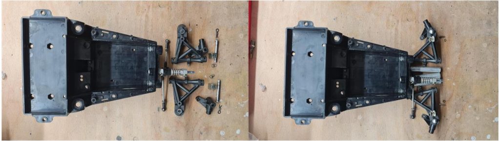
Now that all the parts are clean, the chassis assembly can begin. Start with the front section, which consists of the steering system, the bumper and the suspension system. The first component to assemble is the steering column, including the servo saver system and its tie rods. On this model, the steering tie rods are equipped with standard joints featuring internal ball bearings.
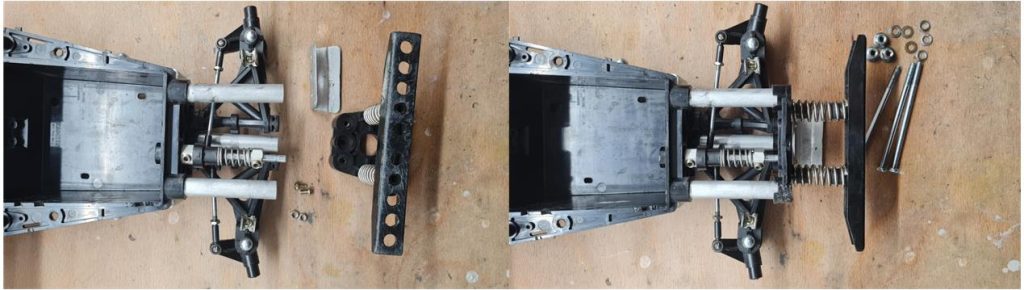
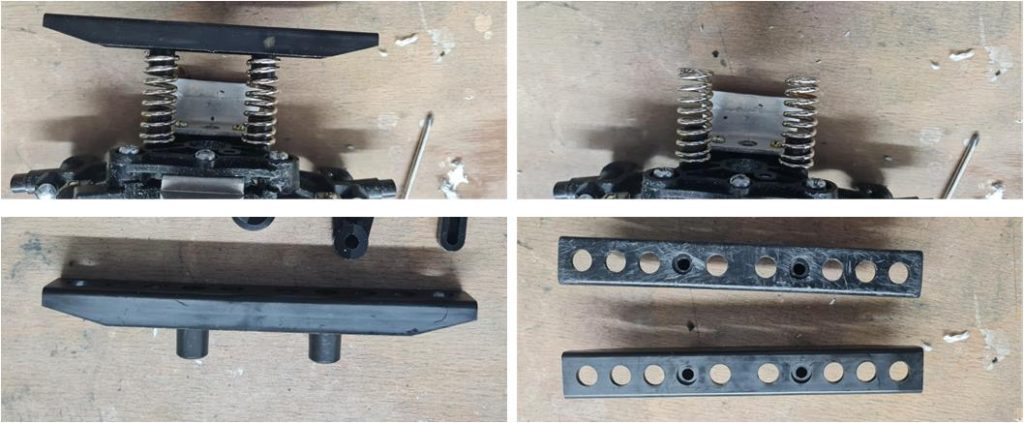
Once the steering column is installed, assemble the three aluminum tubes that form the suspension chassis. Attach the bumper to this system, which features a clever spring mechanism to absorb front impacts. During regular use, impacts tend to deform the L-shaped metal plate. However, the plate can still be used regardless of the degree of deformation.
The shock absorbers are unique to the Wild Willy and Quattro chassis. They are available in two different versions, differing in the attachment of the upper arms. The SWB model features a plastic arm, which is distinct from the LWB and Quattro chassis versions. Once the front mechanical assembly is completed, focus on the electronic components installed within the central chassis shell.
The electronics consist of the servo motor for the mechanical speed controller, which is installed on the aluminum metal plate. The metal plate is secured to the lower plastic shell using two screws. The servo motor for the mechanical speed control is mounted on the plate with double-sided tape and, in turn, the steering servo motor is mounted on the speed control servo motor, also using double-sided tape. One of the two servo motors (the one mounted on top to control the steering) was glued by the previous owner, which unfortunately damaged the surface of the lower shell irreparably.
All the components fixed to the chassis have been installed and the receiver and battery pack for powering the electronics can now be fitted. Once all parts are in place, the upper shell can be secured by screwing in the two screws that firmly attach it to the lower shell. Finally, the battery cables should be soldered to the connector.
Assemble the rear cage that houses the electric motor and the two springs that stabilize the model when it travels on just the rear wheels. The motor features a gray heat-shrinkable plastic sleeve, which is characteristic of the Wild Willy chassis. This sheath is factory-installed on both the short wheelbase and long wheelbase versions.
The rear-wheel drive system and the rear suspension with a rigid axle are quite simple. Similar systems were later studied and developed on other chassis models, such as the Clod Buster.
The front bumper is not in the best condition, showing signs of multiple impacts it has endured. Since a new bumper was available, it has been replaced. In the image on the right of the second row, the old bumper (above) can be compared with the new one (below). The old bumper is intact but marked by time. To replace the bumper, simply detach the old one from the springs and insert the new one. To separate the two pieces, it is necessary to slightly rotate the springs to loosen their grip on the plastic pin.
The rims have been treated with 99% pure alcohol, followed by the application of two coats of fine primer Tamiya 87044 and two coats of matte white Tamiya TS27. The wheels have completed their glycerin treatment. Now they are ready to be assembled with the tires, foam inserts and hard plastic inserts.
Body Restoration
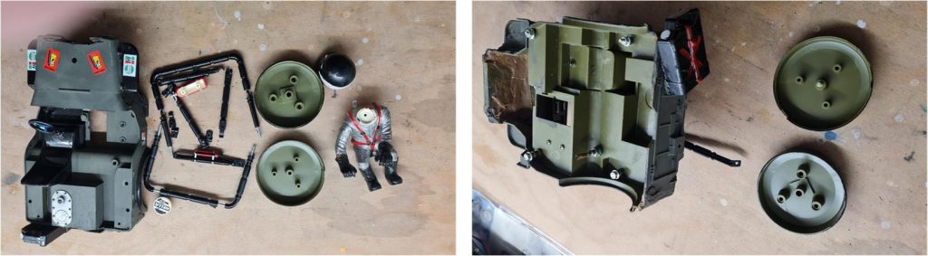
The first step is to remove all the components from the body, such as the roll bar, driver figure, fire extinguisher, rear spare tire and the reserve fuel tank.
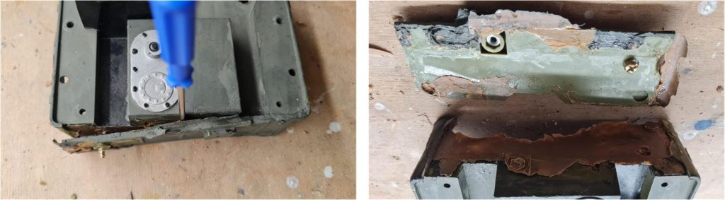
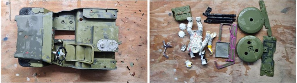
It is evident from the images that resin has been used extensively on both the interior and exterior of the body.
The rear section of the body, where the spare tire and fuel tank are mounted, is a separate piece that was originally screwed onto the main body. However, the excessive use of resin now acts as the adhesive holding the two parts together. To separate the two sections, carefully leverage them apart using a flathead screwdriver, starting from one of the sides. Gradually, the resin will lose its grip, allowing the two parts to be separated without causing any damage.
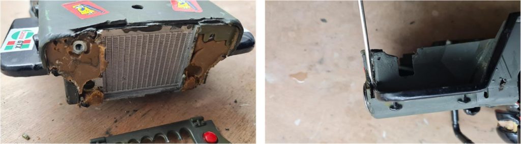
The front section is in significantly worse condition, but the technique remains the same: use a tool, such as a screwdriver, to gently leverage and detach the resin from the body parts.
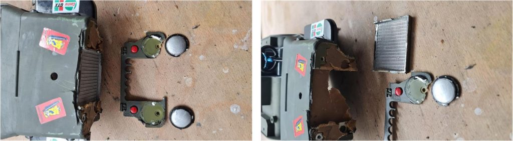
The front grille is in an almost irreparable state, whereas the radiator and the two lights are in good condition.
Some components remain stuck in the resin and must absolutely be retrieved as they could be essential for continuing the restoration. Everything that is recovered won’t need to be reconstructed later, which saves both time and effort.
In the body, at the position corresponding to the passenger seat, a bulb holder has been inserted, which is quite easy to remove.
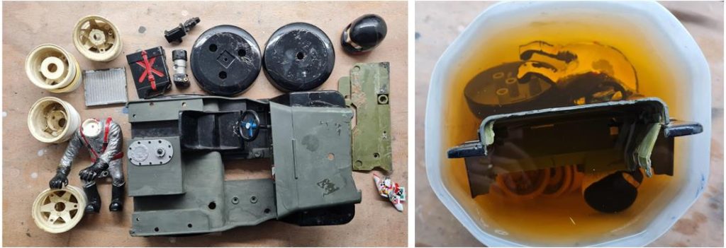
To assess the damage to the body and determine the necessary repair operations, immerse all the plastic parts in 90% pure alcohol (or higher concentrations, as 99% pure alcohol is commercially available), free from dyes and fragrances. In the image on the left, the body and its components are visible with all the stickers removed. In the image on the right, the parts are shown submerged in alcohol. The liquid appears pink-red, likely the result of previous work, as alcohol can be used for various processes. The goal of this phase is to remove paint and degrease the different body components.
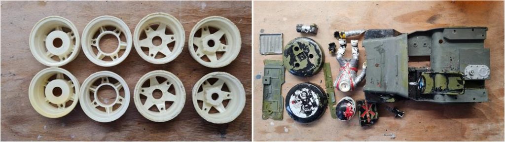
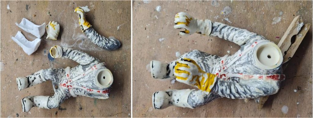
After the first 48 hours, you can take out the parts and remove the initial layer of paint using a kitchen paper towel. The friction between the towel and the surface is enough to strip away any paint that didn’t adhere well. This process can reveal any damage previously concealed by the paint. For example, in this case, the driver’s left hand is damaged, the driver’s left arm detached solely due to the chemical action of the alcohol, the spare tire was painted black without removing the sticker—which is now visible—and the wheels have turned white again, with most of the dirt and grease eliminated. The remaining parts should be immersed in alcohol again for another 48-hour cycle and if necessary, additional cleaning rounds should be performed.
With each application of alcohol, the results improve further. The alcohol also chemically reacts with the glue used to assemble the driver figure and the front grille, making it possible to separate the parts that were glued by the previous owners. Since the container used is not large enough to submerge the entire body at once, the rear section was treated first. The same process should be carried out on the front section once the work on the rear is completed.
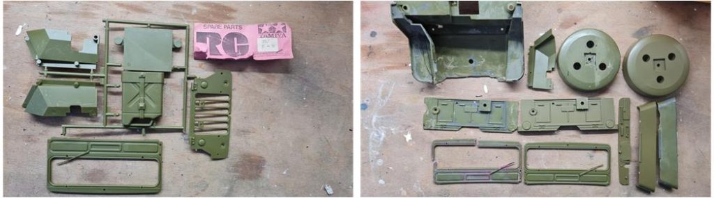
Once the paint has been removed, you can thoroughly assess the damages that were previously concealed. The windshield hinges are missing, having been taken from a donor model. Fortunately, a set of brand-new original C and D parts is available, from which you can replace damaged components such as the front left wheel arch, the two shells of the rear spare wheel, the rear door, the dashboard and the windshield.
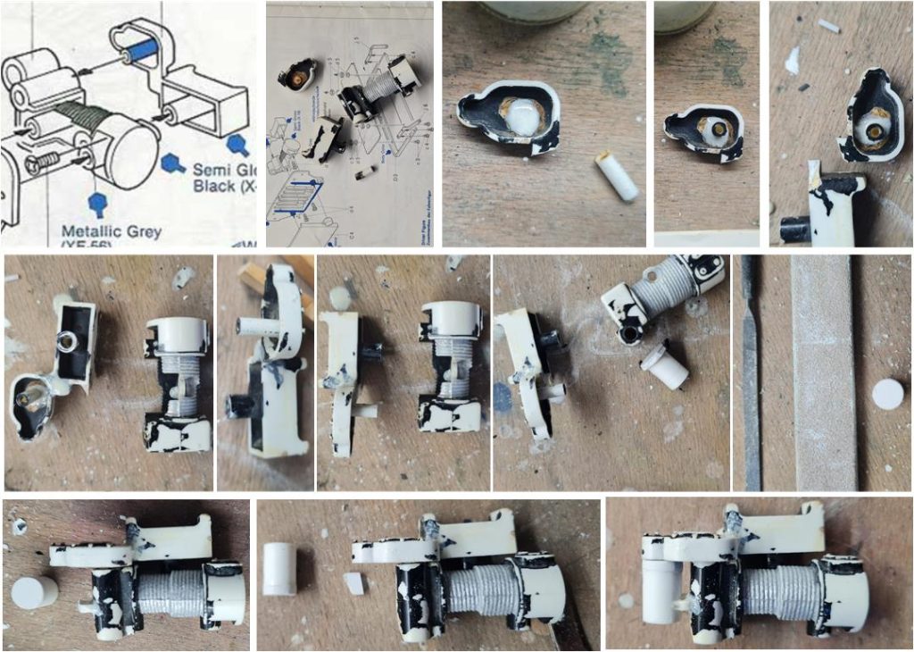
To repair damaged parts that are not available as new replacements, you can fuse the existing pieces together using a solution of acetone and styrene. Acetone dissolves styrene and creates a solution that works as an adhesive between two pieces to be joined. Once the acetone evaporates completely, the pieces are fused together, resembling a cold welding process. Here’s the step-by-step process for repairing the winch:
– The front part of the winch is broken into three pieces. Start by joining the pin to the plate using a drop of the acetone and styrene solution. If the solution is dense enough, it stays where applied; use a brush to pick up the solution and apply it precisely. Since breaks often leave uneven surfaces, the ridges can be used to align the pieces accurately. – After applying the solution, wait for at least 24 hours to allow it to set properly. Then, proceed to join the two pieces that form the front section of the winch using the same solution. The break line serves as a reference for aligning the parts during assembly. Once set (after another 24 hours), smooth the joint with a metal file or sandpaper to remove any excess solution. – Verify that the front and rear sections align and fit together as per the instructions. – A cylindrical part is missing from the rear section. Using pure acetone, create a blind cylinder by melting together a tube of the correct diameter and a small piece cut from a sheet 3–4 mm thick. Use sandpaper or a file to shape the cap into a circular form matching the tube. – Apply a thin layer of the acetone and styrene solution with a brush and fuse the cylinder to the rear part of the winch.
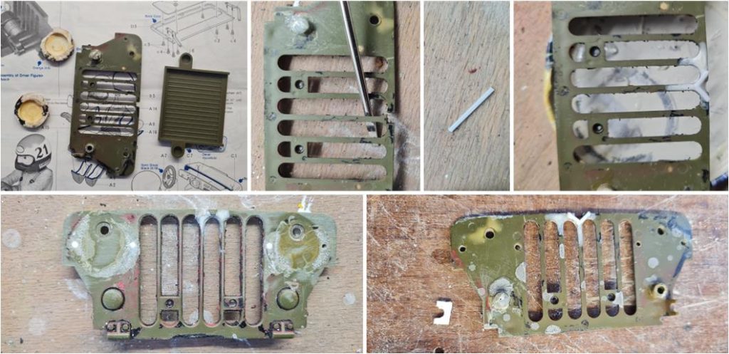
The front section of this model has truly endured significant damage: the grille is broken, the radiator is shattered (as demonstrated in the image where applying leverage with a screwdriver reveals the break), the headlights are poorly positioned and the hood is fractured. Thankfully, the radiator and the two headlights are available as new replacement parts. Here’s the sequence for repairing the front grille:
– Cut two small pieces, 3–4 mm long, from a square rod with a side measurement of 1 mm. – Using a brush, apply a very liquid solution of acetone and styrene to the area needing repair. – Position the two rod pieces so they form a V-shape to bind the broken sections together. The liquid acetone solution will seep into the fracture and weld the small rods to the grille. – Smooth the surfaces using a metal file or 1,000-grit sandpaper to refine the grille’s shapes. – One of the two C plates for securing the grille to the chassis with a nut and bolt is missing. Create a C plate from a 2 mm thick styrene sheet, using the existing plate as a reference. – Fuse the new C plate to the chassis using a dense acetone and styrene solution.
Steps for Repairing the Front Section of the Body:
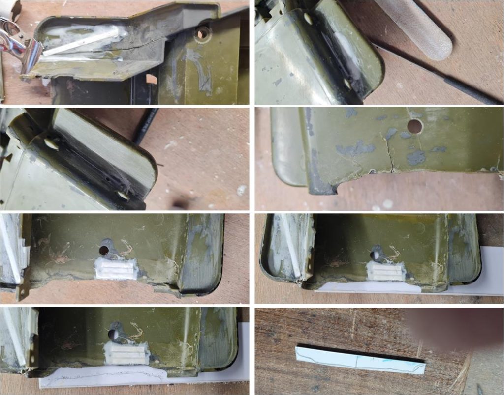
– Cut a piece from a styrene strip, measuring 0.5 mm thick and 3 mm wide, to join the broken sections like a patch. Using a brush, apply a thin solution of acetone and styrene to the underside of the bumper and position the styrene strip there. – Apply the same thin solution to the upper surface using a brush. The solution penetrates the fracture, binding the two parts. – After 24 hours, sand the surface using 1,000 and 1,200-grit sandpaper to remove any excess solution. – Align the broken edges of the hood to match the surfaces. – Apply a layer of acetone and styrene solution on the underside of the body at the fracture point and place three styrene strips (0.5 mm thick and 3 mm wide) to reinforce the repair. The solution penetrates the fracture, strengthening the bond. – Using the chassis as a template, outline the missing hood section onto a 3 mm styrene sheet with a pencil. – Cut the outlined shape from the styrene sheet to create the replacement piece. – With a brush, apply acetone solution along the fracture and on the edge of the replacement piece to be joined to the body. – Position the piece in place on the body, ensuring alignment.
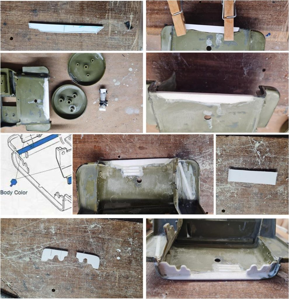
– Use two wooden or metal clips (avoid plastic clips as they melt upon contact with the acetone and styrene solution) to hold the new part in position on the chassis. – Apply a layer of dense acetone and styrene solution along the exposed fracture line (the part not covered by the clips). – After 24 hours, remove the clips and reapply the dense solution along the fracture line multiple times until the solution completely fills the gap between the chassis and the new part. – After another 24 hours, sand the surface using 1,000 or 1,200-grit sandpaper to eliminate any defects or excess material. – The two lateral flanges (right and left) required for installing the front grille to the chassis are missing. Use a 3 mm thick styrene sheet to cut a strip of the correct height and carve out the two parts based on the marks left by the original flanges on the body These marks reveal approximate dimensions and the grille itself can be used as a reference to finalize the shape. – Use the dense acetone and styrene solution to fuse the new flanges to the chassis. Position them based on the original marks left on the chassis. Alternatively, use the front grille as a guide to determine the correct placement. – Smooth the surfaces with 1,500-grit sandpaper to remove any imperfections and ensure a clean finish.
Here’s the process for repairing the broken gear lever:
– If a new gear lever is available, start by removing the remaining small portion of the old lever. – Use wire cutters (tronchese) to carefully cut away the piece attached to the body. – Use a hand drill to create a small hole at the base of the lever’s attachment point.
Steps for Repairing the Dashboard
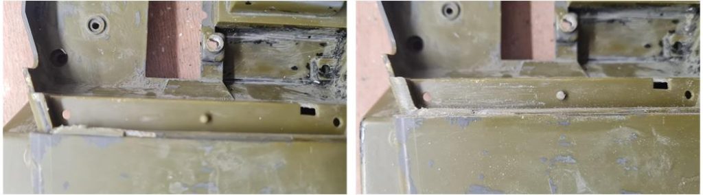
– Use a flat metal file to work on the surface, completely removing any remaining parts of the old dashboard that are stuck to the body, – Follow the demarcation line with the metal file, working along the step-shaped contour on the body, – Use 1,200 and 1,500-grit sandpaper to smooth the surrounding surfaces, eliminating any imperfections.
Steps to Repair the Rear Left Corner of the Body
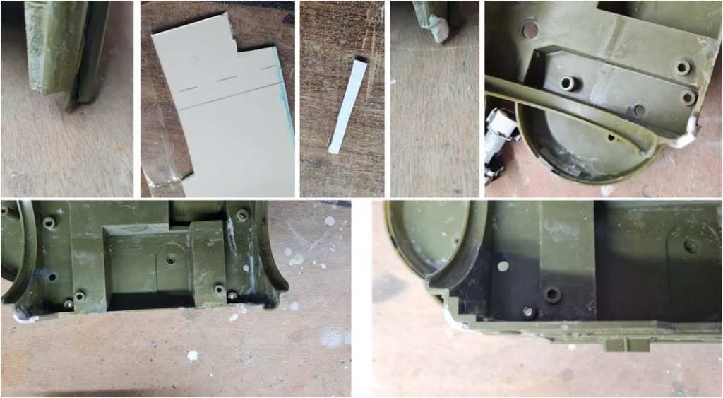
– Use a fluid version of the acetone and styrene solution and apply it to the crack. The solution will seep into the fracture and weld the broken parts together. – If necessary, gently force the two edges of the crack apart to allow the solution to penetrate deeper into the fracture. – Once the solution has set, sand the area using 1,200 and 1,500-grit sandpaper to remove any imperfections and create a smooth finish.
Steps for Repairing the Rear Right Corner of the Body
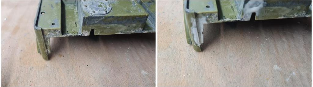
– From a 2 mm thick styrene sheet, cut a strip of the appropriate size to replace the missing piece. – Apply a layer of dense acetone and styrene solution to the damaged area. Position the cut piece onto the repair site. – After 24 hours, use a metal file to shape the external and internal surfaces of the repair to match the form on the opposite side. – Smooth the area using 1,200 and 1,500-grit sandpaper to eliminate any imperfections and achieve a polished finish.
Steps for Repairing the Rear Wheel
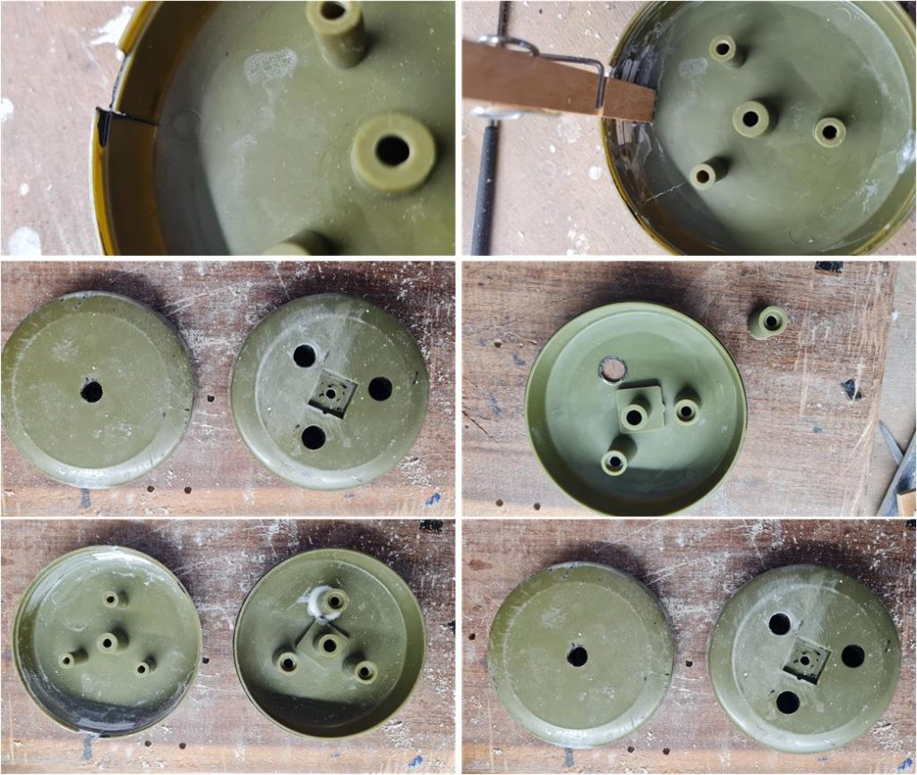
– Use a brush to apply a liquid acetone and styrene solution along the two cracks on the outer belt of the internal shell. – Force the plastic slightly apart to allow the solution to penetrate deeper into the fractures. – Place one or two styrene strips (3 mm wide and 0.5 mm thick) transversely over the cracks. – Secure the strips in place with two wooden clips to ensure stability. – Wait 24 hours for the solution to bond the components. Afterward, use 1,200 and 1,500-grit sandpaper to smooth the external surfaces and eliminate any excess material or imperfections. – Use the fracture lines between the broken tower and the shell as a reference to determine the original position of the tower. – Apply a dense acetone and styrene solution to the area. – Position the tower in place and wait another 24 hours for the solution to solidify and fuse the parts. – Once repaired, test that the two shells of the wheel fit together perfectly.
To finalize the restoration process:
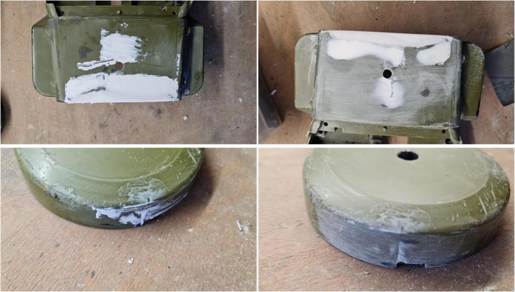
– Apply a thin layer of putty over all the repaired areas. – Allow it to cure for 24 hours. – Sand the surfaces using 1,500-grit sandpaper until the putty is completely removed. If the repair has been properly executed, the putty should disappear entirely, leaving the surface smooth and flawless.
The images illustrate this beautifully: the first row showcases the hood, while the second row depicts the rear shell of the spare wheel. On the left, the putty has just been applied and on the right, the surfaces have been refined with sandpaper.
To repair the driver’s figure:
-Use the liquid version of the acetone and styrene solution for its superior penetration, as it can effectively bond the thin and delicate parts. -Position the broken hand, detached arms and missing sections of the boots carefully. Apply the solution to each joint, ensuring the liquid seeps into the contact areas to create a strong bond. – Allow the solution to work for at least 24 hours to ensure the parts are securely fused together. – Once the bonds are set, refine the surfaces using 1,200 and 1,500-grit sandpaper to remove any excess solution and smooth the repaired areas.
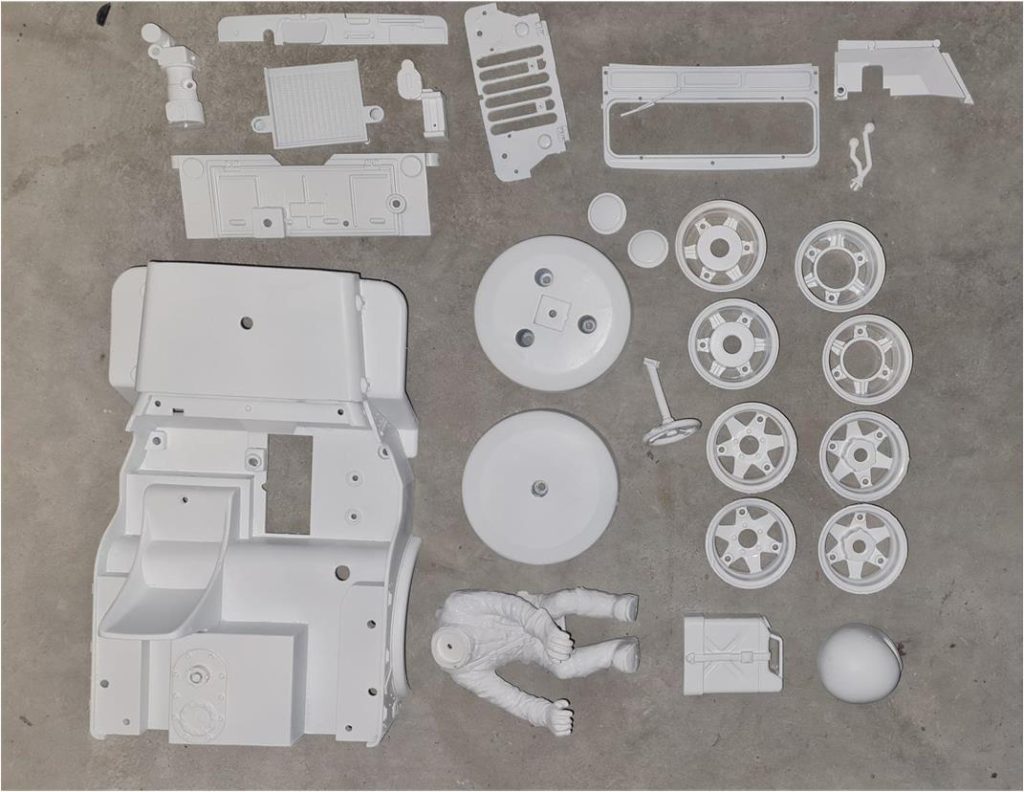
These are the parts after three coats of fine white primer Tamiya code 87044 have been applied.
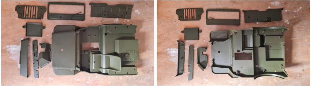
Top and bottom view of the parts that have been coated with multiple layers of olive green Tamiya TS5. The coats have been applied to all internal and external surfaces.
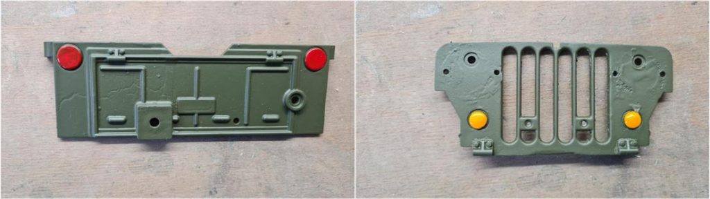
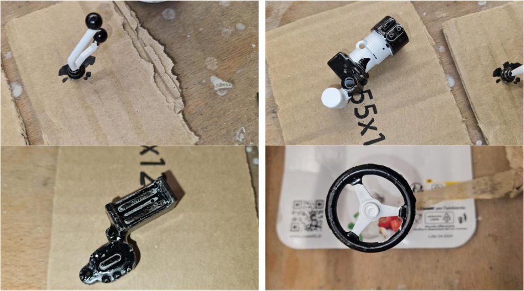
Prepare the following flat effect colors: – X2 White for the pilot’s helmet or alternatively TS26 White – X3 Royal Blue for the driver’s helmet stripe – X6 Orange for the two turn indicators on the front grille – X7 Red for the fire extinguisher installed on the driver’s side roll bar, the top shell of the driver’s helmet and the right and left reflectors on the rear body – X8 Lemon Yellow for the fuel canister installed on the rear hatch – X10 Gun Metal for the radiator behind the front grille – X11 Chrome Silver for the two front headlights – X18 Semi Gloss Black for the winch, steering wheel, windshield gasket, wiper, circular rim of the two front headlights, driver’s seat belts, visor opening contour of the driver’s helmet, gear and reduction knobs, right and left rear wheel covers
Prepare the following matte effect colors:
– XF2 Flat White for the pilot’s suit, or alternatively TS27 Matt White – XF7 Flat Red for the driver’s two gloves – XF8 Flat Blue for the upper part of the seat belts – XF10 Flat Brown for the driver’s boots – XF16 Flat Aluminium for the diesel tank cap, fire extinguisher nozzle, NOS bottle nozzle and the straps for the NOS bottle and fire extinguisher – XF23 Light Blue for the nitrous oxide (NOS) bottle – XF56 Metallic Grey for the hook, steering hub, winch cable, gear lever and reduction lever – XF57 Buff for the spare wheel cover, or alternatively TS46 Light Sand
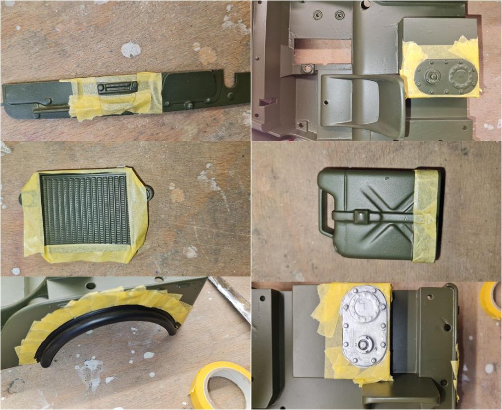
Once all colors are prepared, mask the parts to be painted and begin applying the different coats of paint. Press the masking tape firmly with your fingers to ensure it adheres well to the surface. Avoid any gaps between the tape and the surface, as this would allow paint to seep in and create unwanted streaks.
General rule: apply multiple coats for each color until the final hue fully covers the surface. Always brush in the same direction, go over the painted area several times to spread the paint evenly and wait at least 12 hours between each coat.
Applying color to the turn signals, brake lights, reflectors and windshield gasket requires a steady hand and a small brush. Use paint sparingly to avoid overapplication—it is better to go over the area multiple times rather than risk staining the body.
For very small parts where masking is impossible, it’s best to secure them onto a piece of cardboard and proceed with applying the colors. This provides a stable surface, making the painting process more controlled and precise.
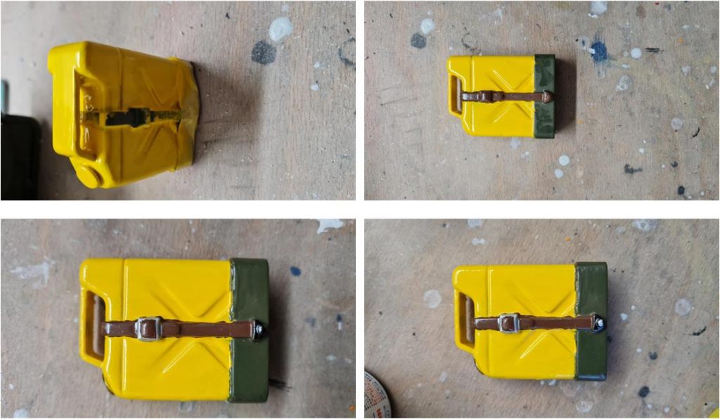
Sequence of images showing how to apply various colors to the fuel can: – Mask the can; press with your fingers to ensure the tape adheres well to the surface, preventing yellow streaks from seeping between the tape and the surface. – Apply flat yellow X8 to the can; the yellow must completely cover the olive green. – Remove the masking; if there are no yellow streaks on the olive green, proceed. Otherwise, spray olive green TS5 onto a piece of cardboard to use as a painter’s palette; use a brush to apply the green and cover the yellow. – Apply matte brown XF10 to the strap (glossy brown X9 can also be used). – Apply Semi Gloss Black X18 to the cap and the buckle of the strap (the small triangle located at the bottom of the can). – Apply gray X11 to the buckle of the strap and the screw that secures the strap. – If too much gray is applied to the buckle, it will cover the brown rectangle of the strap. After 12 hours, reapply matte brown XF10 to the rectangle.
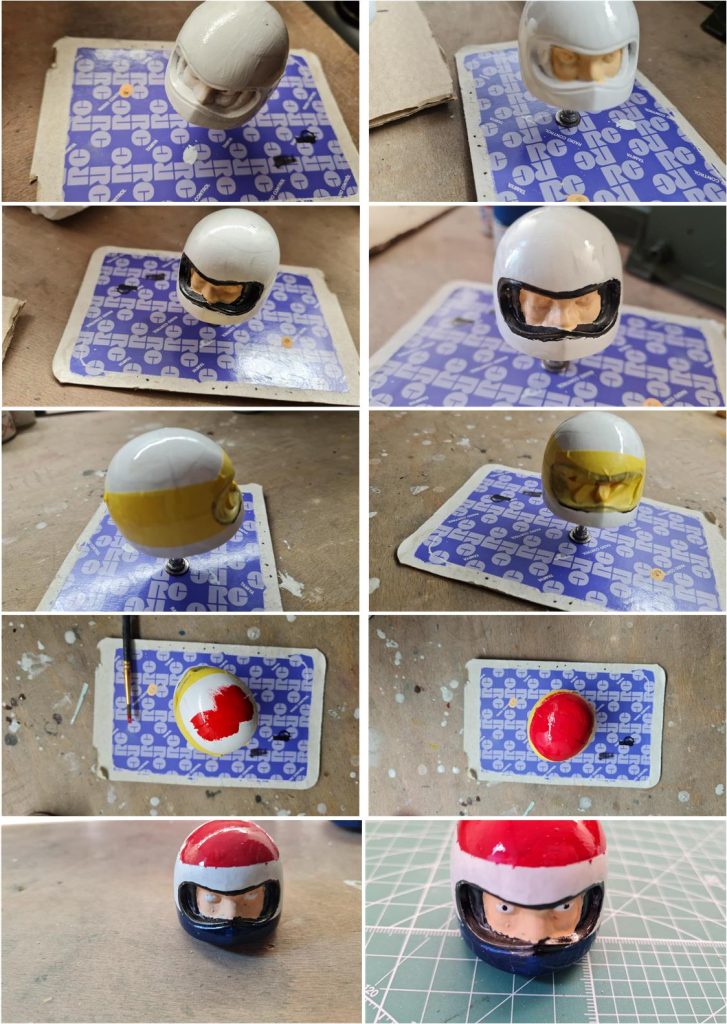
Sequence of images showing how to apply colors to the helmet and face of the little pilot:
– Apply glossy white X2 to the helmet of the little pilot (if desired, TS 26 can be used), – Apply pink to the face (there are many alternatives for the pink face color available on the market, choose the one you prefer), – Apply matte black X18 inside the visor, taking care not to cover the pink, – Mask the helmet, leaving the red and blue stripe exposed; as in previous steps, press the tape firmly with your fingers to ensure it adheres perfectly to the helmet and prevents paint from seeping through, – Apply glossy red X7 and glossy blue X3. Be careful—with the helmet shell, it’s better to start applying the color from the center and move outward towards the masking tape. This way, the color is less likely to seep between the surface and the tape, – Apply the face color—many skin-tone paints are available on the market; select the one that best suits your taste, – Using the toothpick-tip technique, apply the flat white XF2 for the eyes and matte black X18 for the pupils.
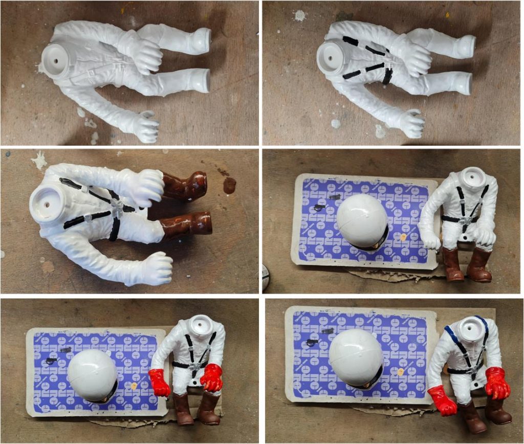
Sequence of images showing how to apply colors to the pilot figure:
– Apply matte white XF2 to the body; TS27 can also be used. – Apply Semi Gloss Black X18 to the seat belts. – Apply flat gray X11 to the seat belt buckles. – Apply matte brown to the boots. – Apply matte red XF7 to the gloves. – Apply matte blue XF3 to the rubber reinforcements on the upper part of the seat belts.
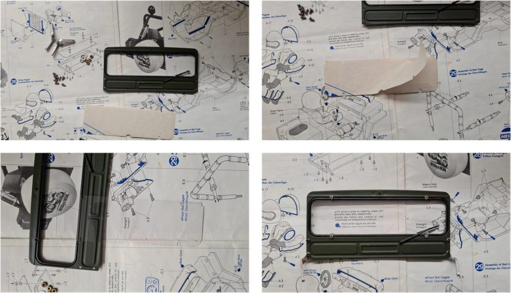
Assemble the windshield with the glass. The glass is a shaped piece of plexiglass; in this case, a new original piece is available, with the two protective films still applied. Screw in the four nuts and bolts that secure the glass to the windshield, then attach the two supports that serve as hinges. Once installed, the plexiglass is so transparent that it is almost invisible.
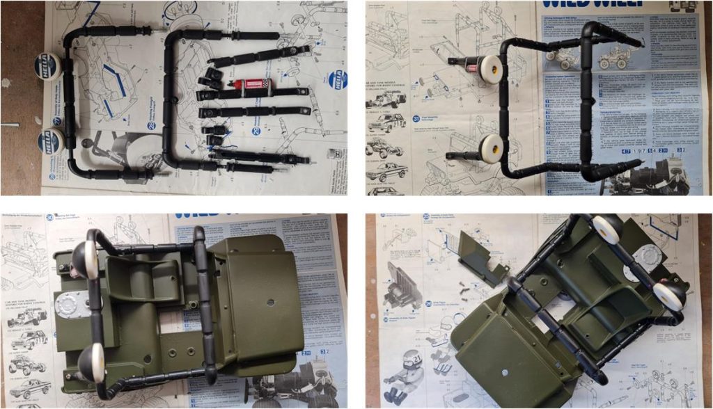
Prepare and install the roll bar using the original parts, which are in good condition. They show signs of rollovers, but overall, they are in proper shape.
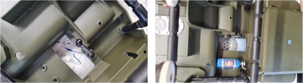
Install the NOS cylinder using the two screws and the shortened gear lever.
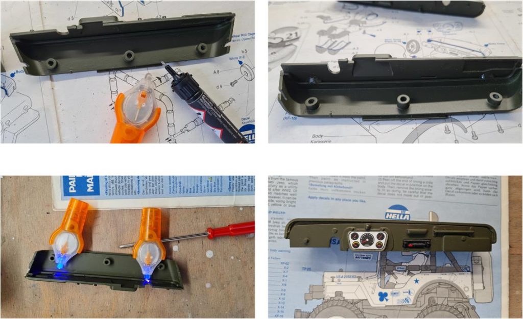
Glue the instrument panel – radio – glove compartment to the dashboard using an adhesive that hardens when exposed to UV rays. Apply two drops at the ends of the parts to be glued, without overdoing it. Once hardened, this adhesive remains very elastic and if necessary, the parts can be separated by scoring the surface with a utility knife.
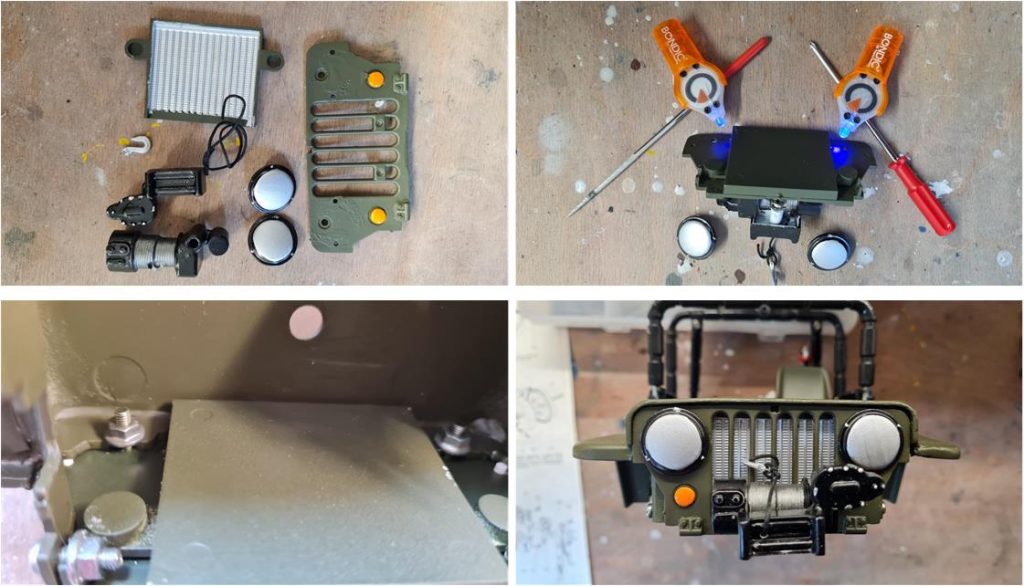
The front winch consists of several parts and it is necessary to obtain a piece of black wire to simulate the hook cable. The radiator and grille must be glued together; as with the dashboard, UV-curing adhesive was used. This adhesive has several advantages: once cured, it remains flexible, only solidifies when exposed to UV light—allowing time to correctly position the parts before bonding—and requires application only in specific points to secure the components. After installing the winch onto the grille, the grille itself must be mounted onto the chassis. At this point, the chassis was severely damaged, but the two parts fit perfectly, meaning the repair was executed correctly.
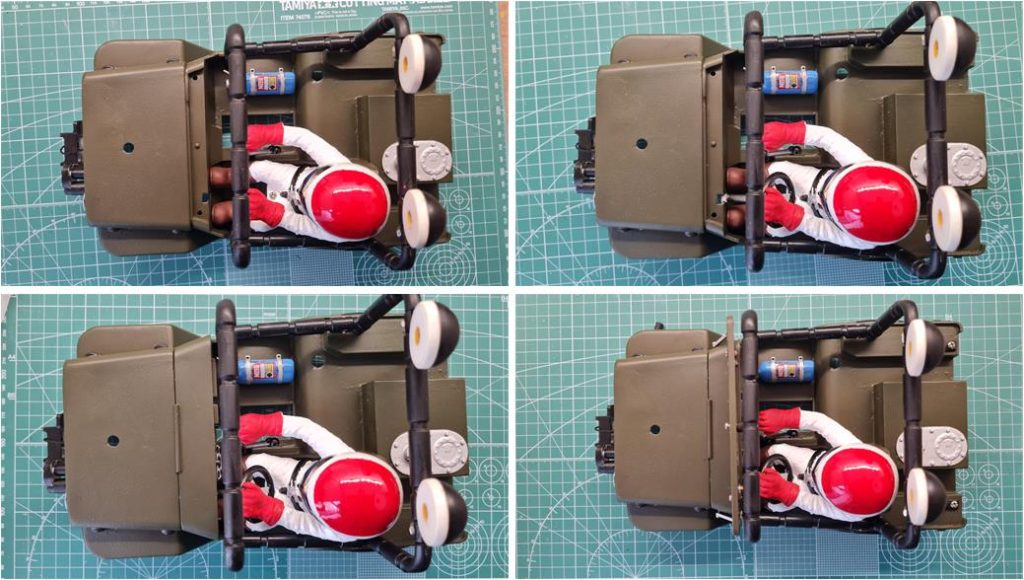
Complete the cockpit by installing the pilot figure with the steering wheel. The steering wheel is equipped with a column that fits into the main body of the chassis. The pilot figure and steering wheel must be inserted together into the cockpit; space is limited, so they need to be positioned simultaneously. The steering column is meant to be glued to the chassis, but the installation is so precise that it remains securely in place, making the application of glue unnecessary. After installing the pilot figure and steering wheel, position the dashboard and fasten it with two screws. The windshield requires two screws to function as hinges and a third screw secures it to the roll bar.
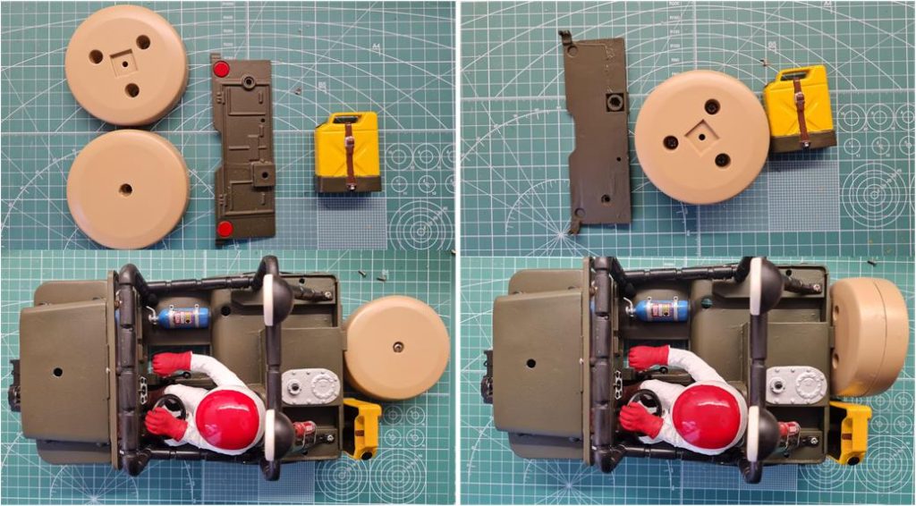
To complete the chassis, only the tailgate with the spare wheel and the reserve fuel canister is missing. All parts have been painted and it is necessary to assemble them onto the chassis. The order to follow is precise:
– Install the fuel canister on the tailgate and insert the nut into the designated compartment, which will be used for the spare wheel bolt. – Attach the assembled unit to the chassis using three nuts and bolts (one central and two lateral). – Assemble the spare wheel with three self-tapping screws. – Install the spare wheel onto the chassis with the central screw.
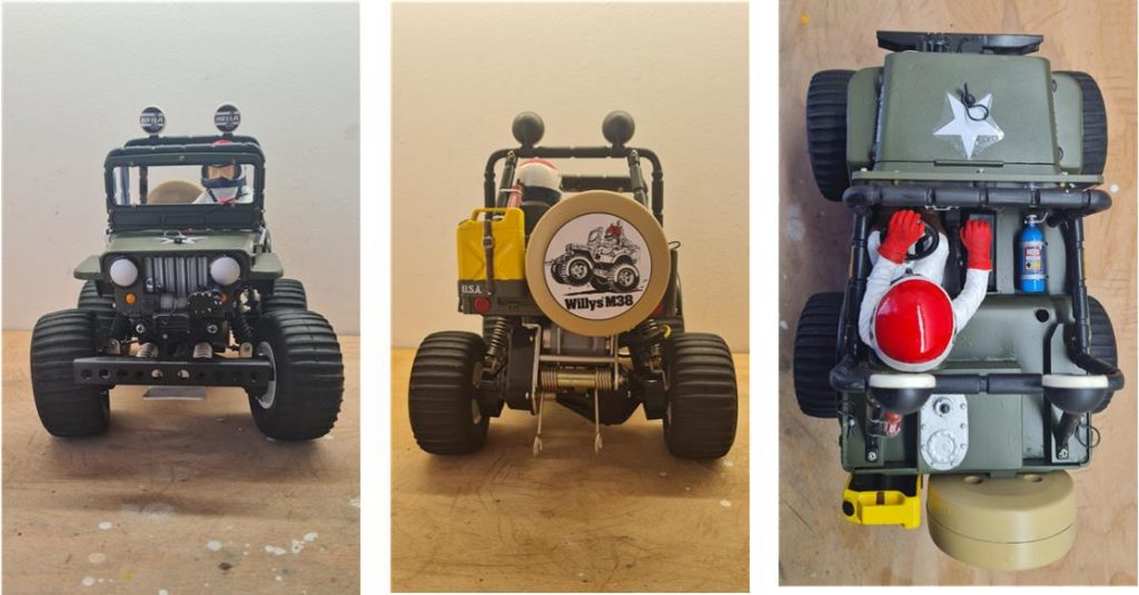
Now it is possible to join the body to the frame; only the stickers are missing.
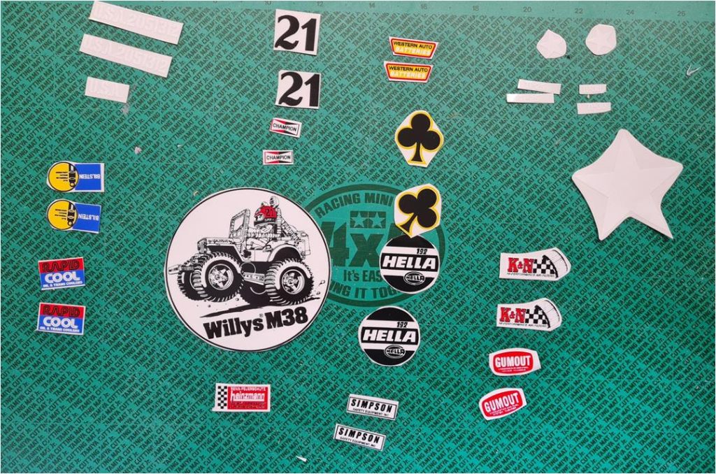
The final step is to prepare the stickers and apply them.
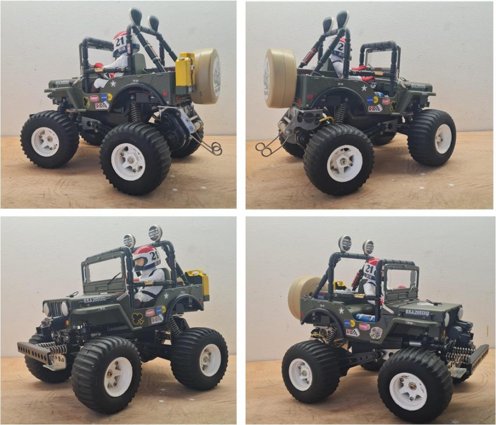
Restored model
Images showing the finished model.
Tamiya, original figure, box art, guide book and catalogue are of TAMIYA INC, which does not endose or sponsor www.tamiyaclassic.com. Any brands, logos and trademarks represented on this website are the copyright of their respective owners.