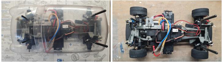
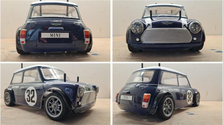
Tamiya Rover Mini Racing, item number 58211, released in 1998 and available on the market until 2010. Lexan body without styrene accessories. M-03 chassis with front-wheel drive.
Analysis of the model to be restored
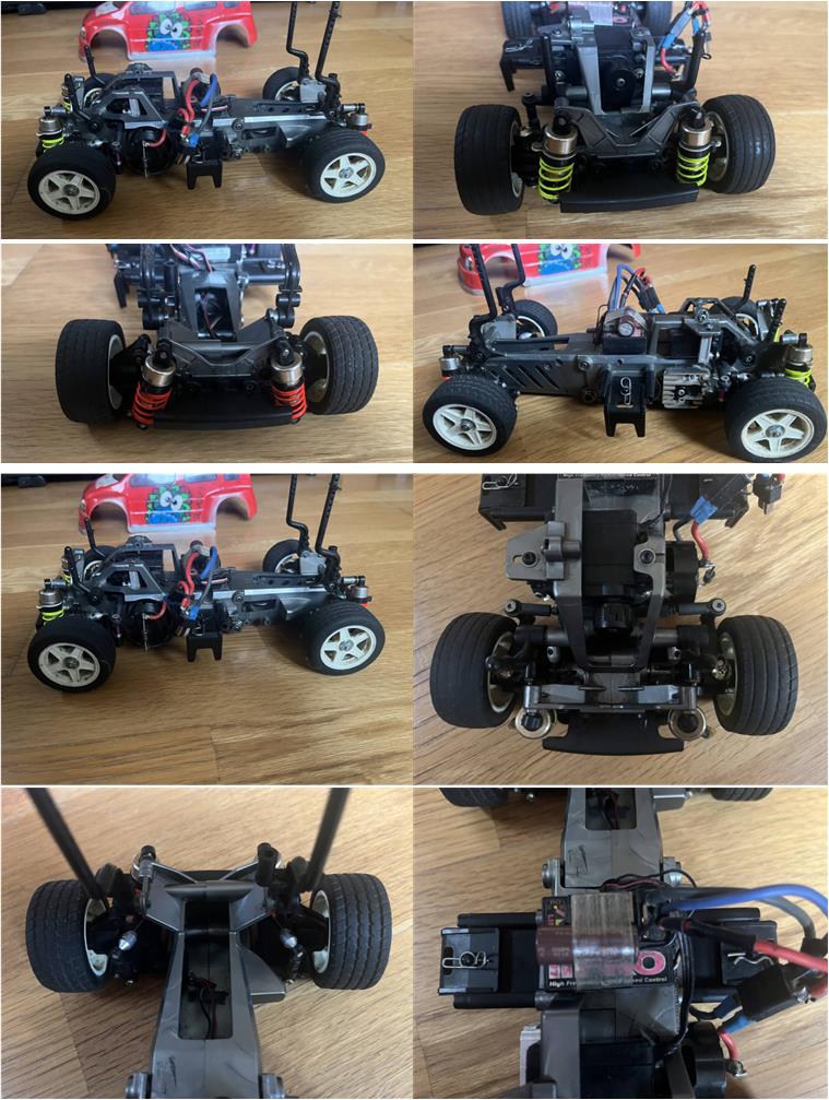
The listing provides the following information: “The M-03 model is equipped with various options such as ball bearings, ball differential, aluminum alloy shock absorbers, Wagon R Suzuki body, drive shafts, front and rear stabilizer bars. Originally it was a Toyota Bb Buddy, so a chassis for M-03L models is also available.” The photos in the listing allow for an assessment of the model’s condition, confirming the stated details: not a new model, equipped with some accessories to improve performance. Based on the photos, it can be assumed that the rims and tires appear to be in poor condition.
Upon arrival of the package, the condition of the lot can be directly verified; in fact, the listing is inaccurate for several reasons. The package does not include the two half-shells needed to extend the chassis from the standard wheelbase (210 mm) to the long version (239 mm). The body is presumably the Suzuki Wagon R by HPI. On the other hand, the lot includes items that were not mentioned in the listing and were not shown in the photos:
– instruction manual for model number 58265 Toyota bB, – instruction manual for model number 58211 Rover Mini Cooper Racing, – one new package of set 50793 described as “M03 C Parts (Suspension Arm)”, – two new packages of set 53334 described as “Low Friction Damper V Parts”, – one new package of set 50875 described as “5 mm Ball Connector 4 pcs” and – one new package of set 50591 described as “5 mm Ball Collar Set”.
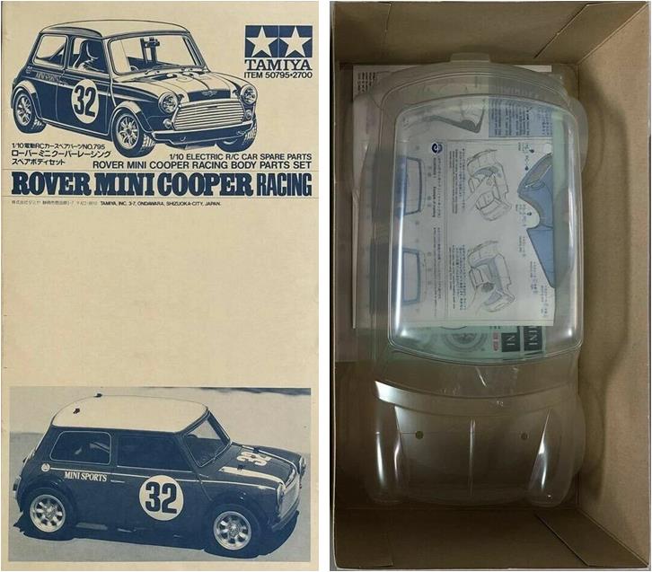
After verifying the contents of the lot, the restoration project can be assessed: restore the chassis to factory condition while retaining the performance-enhancing accessories installed by the previous owner. The body chosen to match this chassis is item code 50795 described as “1/10-Body Mini Cooper Racing”: a replacement body shell complete with stickers for the Rover Mini Cooper track racing version. This body shell was selected because the manual for model 58211 is included in the lot.
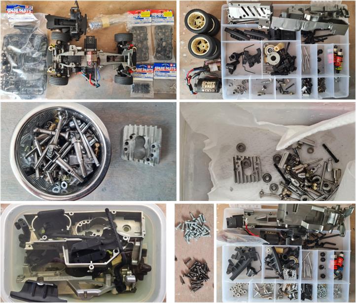
Chassis Restoration The restoration begins by disassembling the chassis completely to sort the parts into homogeneous groups (image on the right in the first row): metal, plastic and rubber. Each material is regenerated through a process specific to its type. Rubber is only found in the tires, which will not be used for this restoration, so they are stored on shelves. The tires are in terrible condition: so dry they crack upon touch. The rims are in good condition, but the tires are glued to the plastic. The metal parts are soaked in diesel fuel (the parts before treatment are shown in the image on the left of the second row and the parts after treatment are shown in the image on the right of the second row). The soaking period lasts one week to allow the diesel to chemically attack oxidation and grease. After this period, the parts are scrubbed with a hard-bristle toothbrush to remove the remaining encrustations. Once this process is complete, the metal parts are left in the sun for two days to allow the diesel to evaporate. The metal surfaces are now nearly like new, with a thin oil film remaining to protect them from oxidation. The plastic parts are soaked in a solution of water and dish soap (image on the left of the last row). The treatment lasts three to four days and can be carried out in parallel with the metal parts treatment to optimize processing time. After the soaking period, the parts are scrubbed with a hard-bristle toothbrush to remove the remaining encrustations. Rinse the plastic parts and leave them in the sun for one day. The screws installed on the chassis are made of dark alloy and are replaced with the original ones (image in the center of the last row), which are made of light metal. At the end of the regeneration process, the parts are organized and ready for assembly (image on the right of the last row).
Several performance-enhancing accessories are installed on this model:
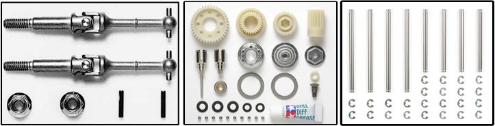
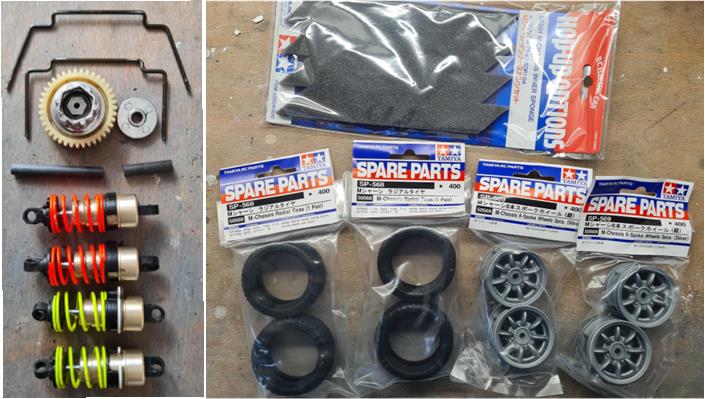
53068 – Sport Tuner Electric Motor 53205 – pair of universal front drive shafts for M-Chassis (shown on the left in the images below) 53267 – ball differential for TA-03 (shown in the center in the images below) 53301 – stainless steel suspension shafts for the four lower arms (shown on the right in the images below)
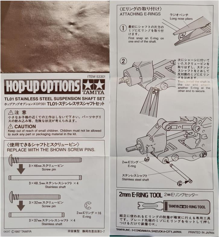
The image below shows the instruction manual for the stainless steel suspension shafts set number 53301.
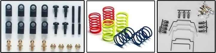
53303 – four adjustable upper suspension arms (shown on the left in the images below) 53308 – two aluminum towers for installing the steering servo 53333 – six touring car springs (for short shock absorbers) with three stiffness levels; yellow, blue, red in increasing hardness (shown in the center in the images below) 53343 – front and rear stabilizer bars for M-03 (shown on the right in the images below)
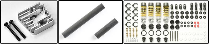
53344 – electric motor heat sink with two screws (shown on the left in the images below) 53348 – complete ball bearing set for M-03 53390 – hollow carbon gear box shaft for M-03, guide for building carbon parts (shown in the center in the images below) 53527 – two titanium turnbuckles 3×32 mm 53571 – four low-friction aluminum alloy shock absorbers, TRF series; gold-colored shock body (shown on the right in the images below)
The condition of the performance-enhancing accessories is good; there are no signs of wear, only traces of normal use (image on the left). As of today (2025), accessory parts to complete the Mini Racing model 58211 are still available on the market (image on the right):
– rims (two sets of 50569 described as “M-Chassis 8Spk Whl Sil”), – rubber tires (two sets of 50568 described as “M-Chassis Radial Tire”) and – inner foam inserts for the wheels (one set of 53204 described as “M-Chassis Inner Sponge 4 pcs”).
Before assembling the chassis, verify that:
– all model parts (including performance-enhancing accessories) have been regenerated, – all non-original components have been replaced (such as hardware), – all missing parts (such as wheels, rims, etc.) have been sourced from the market.
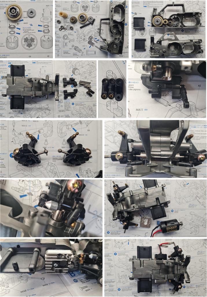
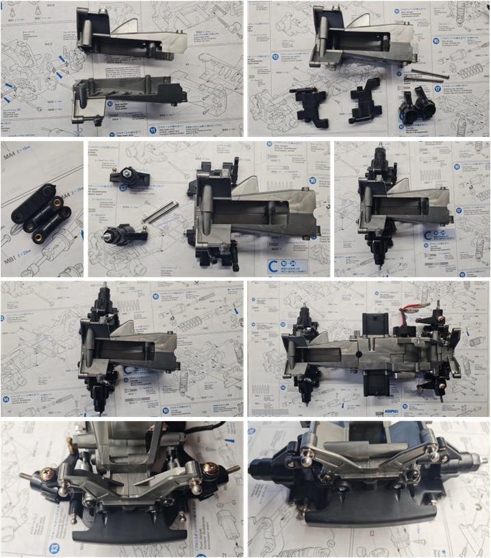
The chassis is divided into two main sections: front and rear. To assemble the chassis, the manual instructs to begin with the front section, which includes the steering system, suspension system, electric motor and gear box. The background of the various images below consists of the instruction manual pages. The first step is to assemble the gears and the ball differential inside one of the two chassis half-shells. To build the gear box, the two carbon shafts were used (images in the first row, set number 53390). The chassis consists of two half-shells, to which all other systems are attached, such as the lower suspension arms and the adjustable upper arms (image in the center of the second row, set number 53303; the adjustable arms have the same length as the fixed ones and camber will be fine-tuned based on the track). Assemble the front hubs, which include the drive shafts (image on the left of the third row, set number 53205). For improved road holding, a stabilizer bar is installed on the front suspension (image in the fourth row, set number 53343). To complete the front section of the chassis, install the electric motor with the aluminum heat sink (last row image, item number 53344).
The rear section is simpler than the front, as it includes only the suspension system complete with stabilizer bar and stainless steel shafts (the front and rear stabilizer bars are part of the same set number 53301). As with the adjustable upper arms of the front suspension, the adjustable upper arms of the rear suspension are built by comparing their length to that of the fixed arms (images on the left of the second row). All 5 mm brass ball shafts have been replaced with alloy ones from set number 300050592 (last row image). Once both sections are complete, they can be joined by tightening four screws to assemble the M-03 chassis.
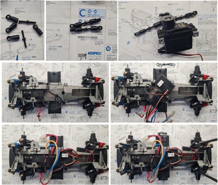
The adjustable steering tie rods (first row image, set number 53527) must be connected to the servo arm equipped with two ball joints. At this point, only the electronics (second row image), the four shock absorbers (set number 53571) and the four body posts remain to be installed.
Now the body can be test-fitted (image on the left) and the wheels installed (image on the right).
Body Restoration
The body is new and includes stickers with masking for the cockpit windows. First, cut:
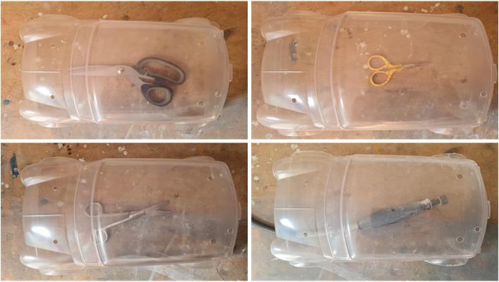
– straight lines using long-blade scissors (image on the left of the first row), – small and curved sections using short-blade scissors (image on the right of the first row), – wheel arches using curved-blade scissors (image on the left of the second row) and – finish all edges with a cylindrical rotary file (image on the right of the second row).
Avoid leaving sharp corners, as these are the points where Lexan body shells tend to crack upon impact. Cracks start from these areas and spread as long fractures. To complete the body shell preparation, wash the inside with warm water and degreasing dish soap to remove residues from the lubricants used during Lexan molding.
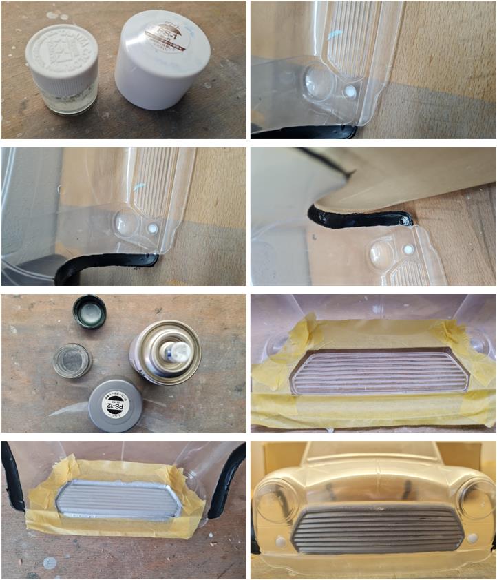
The body requires several colors: PC5 – PS5 black for the wheel arches, PC1 – PS1 white for the nose arrows and roof, PC12 – PC12 gray for the front grille and PS4 blue for the body. Brush-on PC series paints for Lexan are no longer available on the market. White and gray must be applied with a brush because the areas to be painted are too small for spray application. To obtain paint suitable for brushing, release part of the spray can’s contents into a container (first and third row, left side). The paint that comes out of the nozzle is a mixture of pigment and thinner. Wait 24 hours for the paint to settle at the bottom of the container, then remove the surface layer, which is clear thinner. Use a brush to apply the paint to the Lexan body shell, applying multiple coats (five or more). The resulting paint is very diluted and struggles to adhere to Lexan.
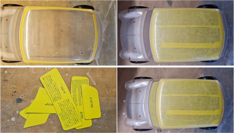
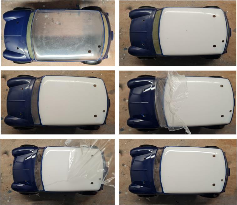
Mask the roof using automotive masking tape: use medium-sized tape to outline the perimeter of the roof (image on the left in the first row), fill the central area of the roof with larger tape strips (image on the right in the first row), the cockpit window masking is included in the body’s sticker set (image on the left in the second row).
Follow this guide to apply colors on Lexan bodies; apply colors from darkest to lightest: first apply the blue, then the white. After applying the coats of blue paint, remove the masking from the roof and apply the white paint. To finish the job, remove the cockpit window masking and the external protective film.
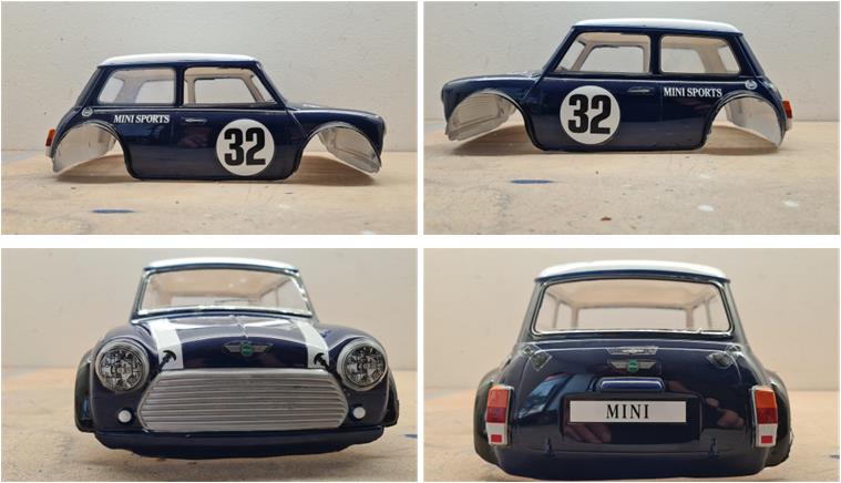
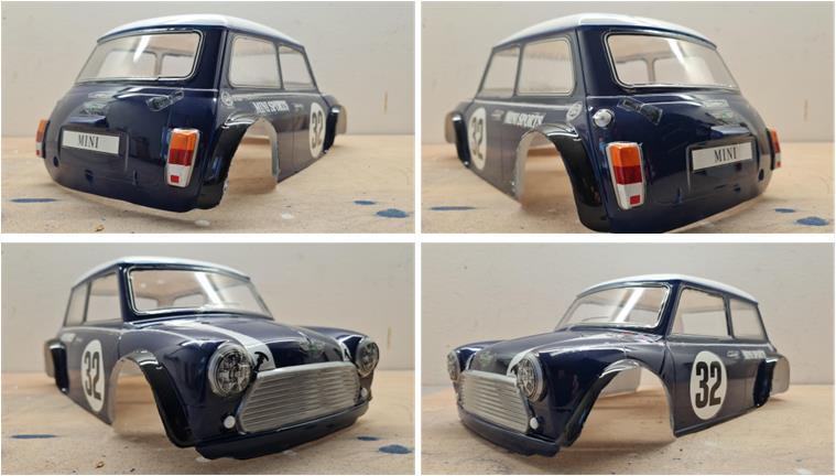
Now the body is ready for decal application.
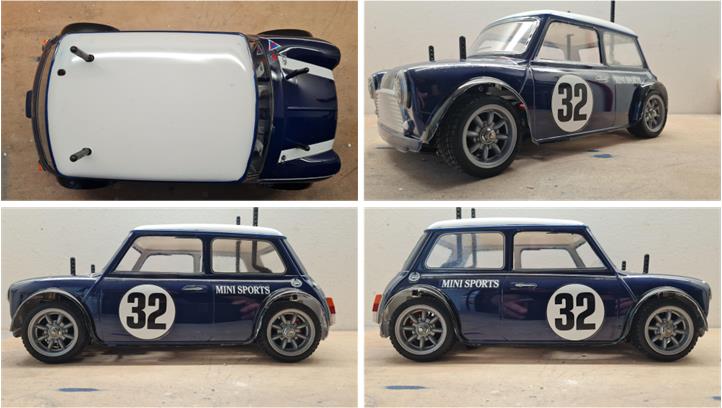
Restored model with body
Tamiya, original figure, box art, guide book and catalogue are of TAMIYA INC, which does not endose or sponsor www.tamiyaclassic.com. Any brands, logos and trademarks represented on this website are the copyright of their respective owners.