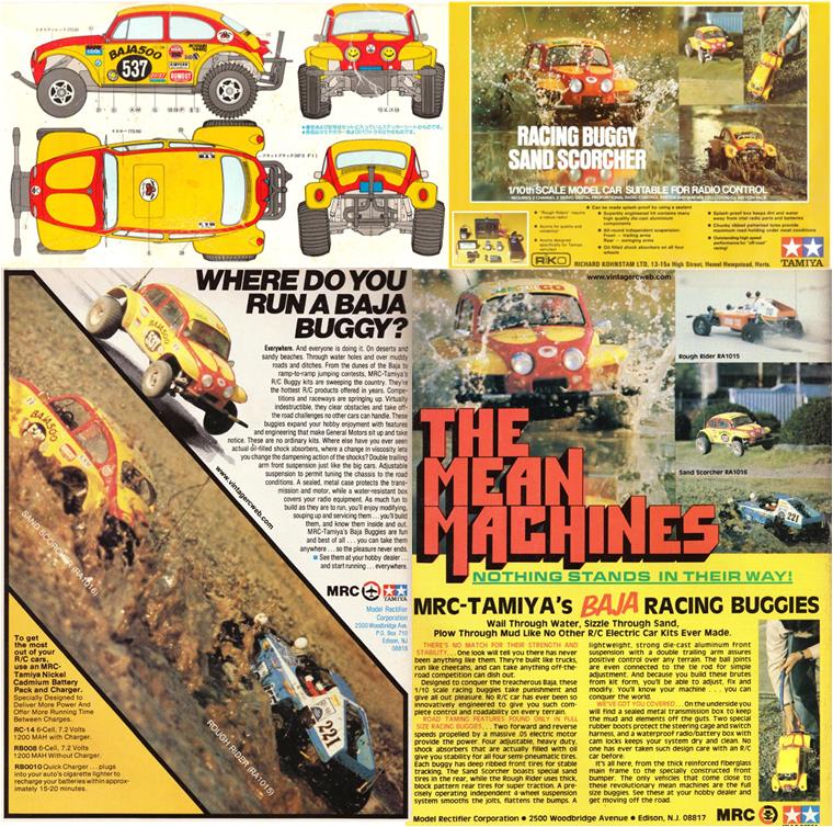
Tamiya Sand Scorcher, item number 58016 released in 1979 and available on the market until 1984. Body made of styrene. SRB chassis.
This model was released on the market with two types of liveries, both of which are iconic:
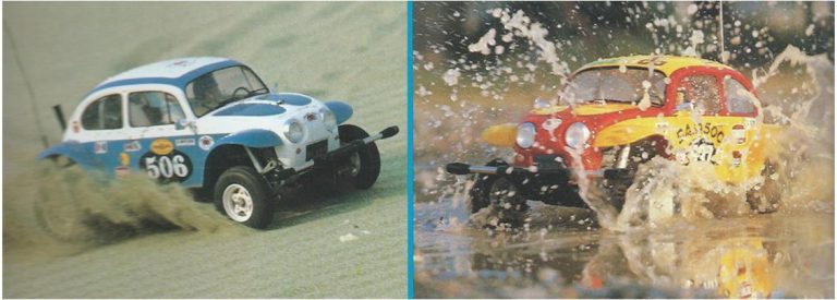
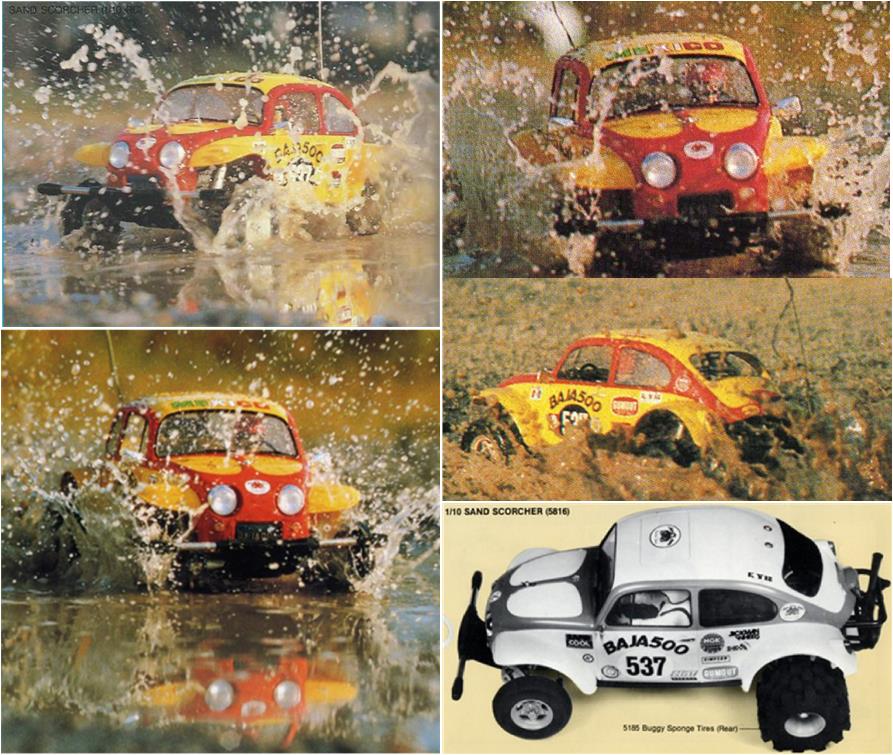
– white racing and light blue livery featured in the catalog (later reused in 2010 for the re-release with item number 58452, making it the most common one) – alternative livery in Italian red (Tamiya code TS8) and dark yellow (Tamiya code TS16) shown in advertisements published in industry magazines (on the left in the image below) and in some pages of guide books released between 1980 and 1983 (on the right in the image below). For this restoration, this color scheme was chosen: the chassis is definitely a Mk1 and this is the livery from the model’s earliest appearances.
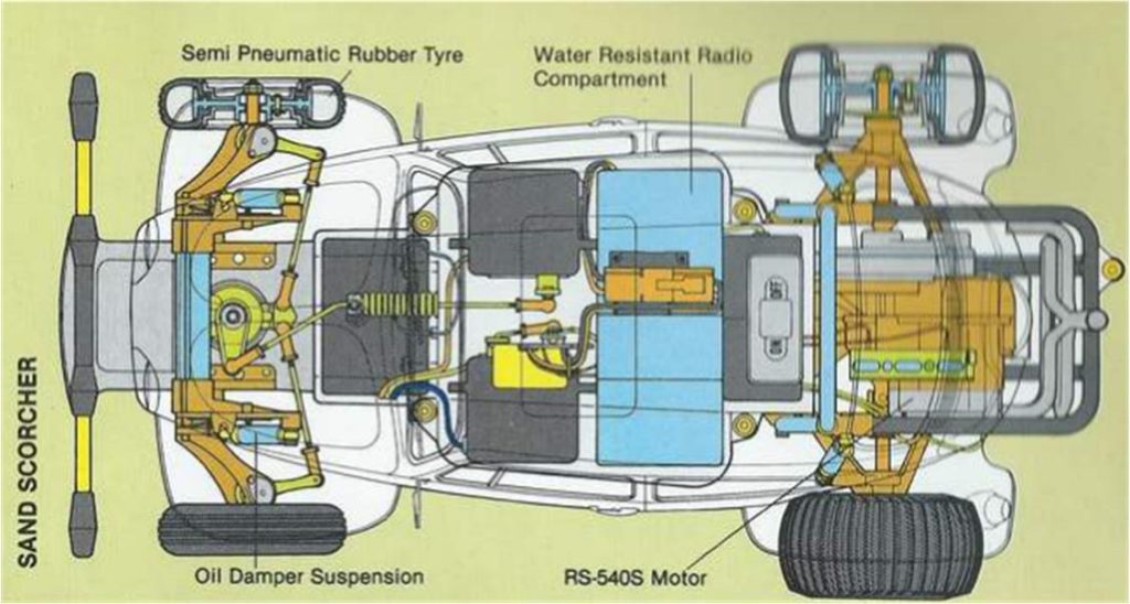
The SRB chassis is a scaled-down replica of the Volkswagen Beetle chassis; Tamiya adopts the layout of the front double wishbone suspension and the independent rear suspension with torsion bars.
Model analysis for restoration
The SRB chassis exists in two versions: Mk1 (the first released on the market) and Mk2. To analyze the differences between the two chassis, refer to this in-depth guide. When purchasing a chassis, it’s important to carefully examine what you’re dealing with, as there are three possible scenarios:
chassis with all components matching the Mk1 version
chassis with all components matching the Mk2 version
chassis with components partially from Mk1 and partially from Mk2: we could call it a mix of parts. The reason for this unordered combination is that Tamiya introduced the Mk2 updates gradually, so some models left the factory with a mix of Mk1 and Mk2 parts. Additionally, owners of Mk1 models often repaired damage using available market parts, which may belong to the newer Mk2 version.
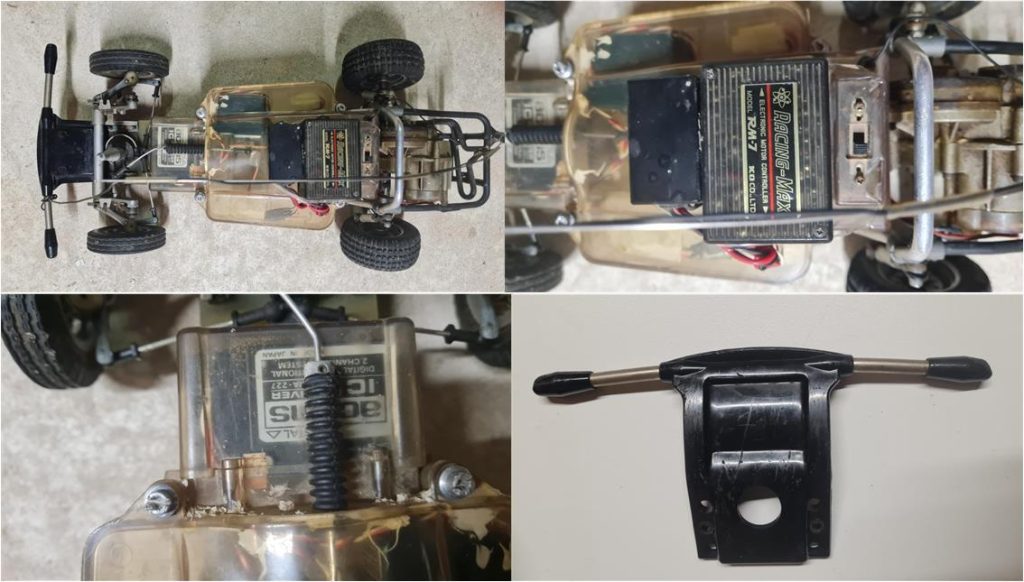
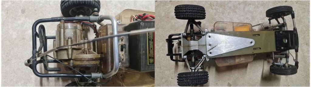
From an initial overview of the model (image on the left in the first row showing the top view), it can already be stated that the rear tires are from the Ford 150 Ranger model number 58027 and the front wheels are not the factory originals from Tamiya. All four wheels will therefore need to be replaced. The electronics box (image on the right in the first row) is light-colored, indicating it’s from the Mk1 version. The electronics box includes the lower tray, upper shell and receiver box (image on the left in the second row). From the top view, the antenna and black front bumper are visible (image on the right in the second row); both parts rarely withstand the test of time: they easily break during normal use and are certain to break after a rollover or frontal impact. The front bumper shows signs of wear with various scratches of different depths. The black front bumper is found only on the Mk1; in the 2010 re-release, the bumper is also black but has a different code and identification marking than the original version. The mechanical speed control resistor is missing, but an early electronic motor speed controller appears to be installed.
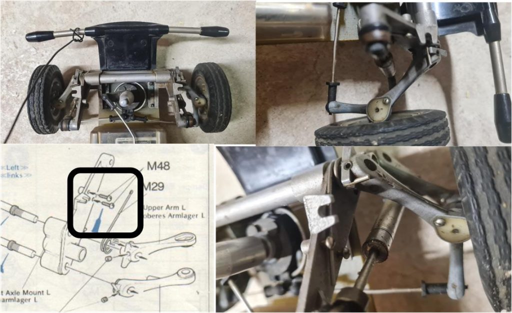
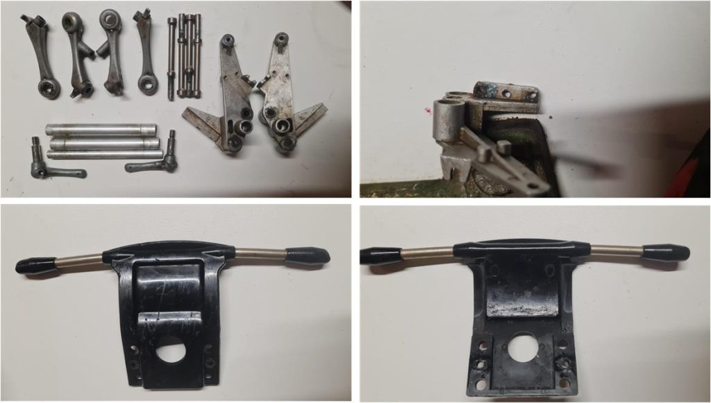
The two lower arms and the two upper arms of the front suspension are from the Mk1 version, recognizable by being slightly thinner (less robust) than the Mk2 version (see images in the first row). The two front suspension towers are equipped with the two screws used to lock the springs (see image on the left in the second row), which are typical of the Mk1 version.
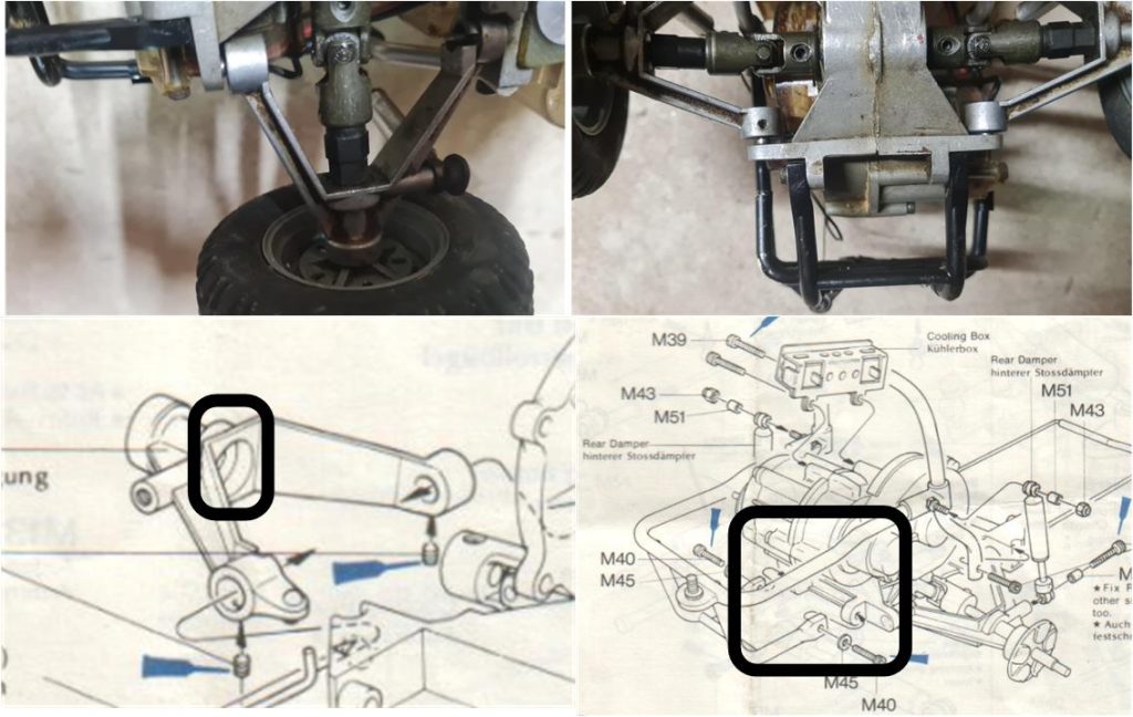
The lower arms of the rear suspension and the two shells forming the gearbox housing are from the Mk1 version. The two drive joints transmitting motion to the wheels are dark-colored (olive tone), indicating they are the ones installed on the Mk1 version. These joints are rare to find because they wear out during normal use. The steel pin grinds down the brass alloy joint until it breaks completely; these pins need to be replaced after a few hours of model operation.
The roll bar protecting the gearbox housing has a section covered with black electrical tape, suggesting that there may be damage underneath. The engine exhaust pipe is also missing. The chassis analysis has led to the conclusion that this is an original Mk1 chassis in all its parts. The condition of the various components will need to be assessed after disassembly. If any damage not visible during the preliminary inspection is found, it will be necessary to look for solutions compatible with installation on an Mk1 chassis.
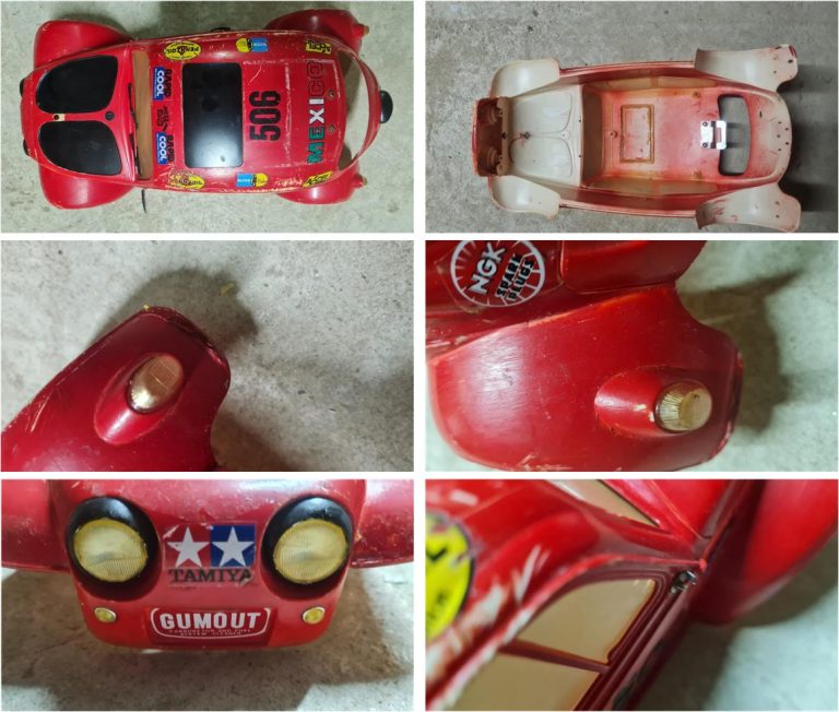
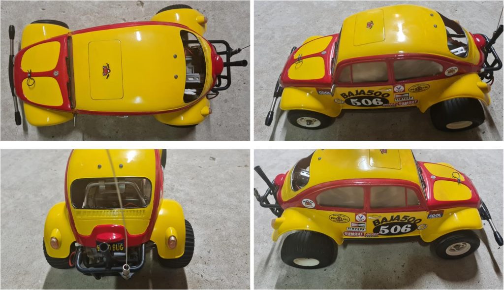
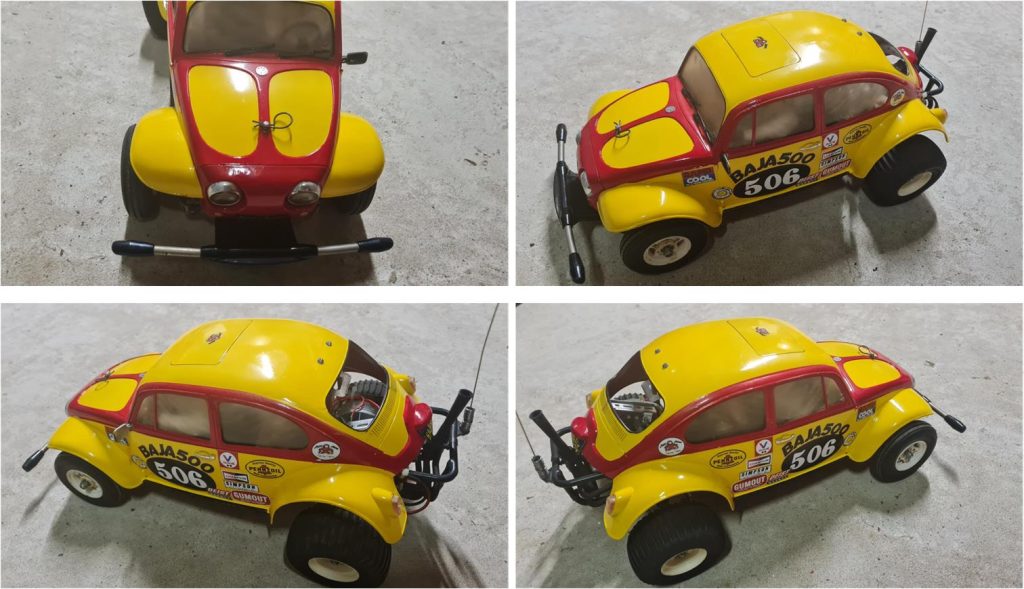
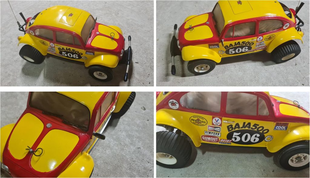
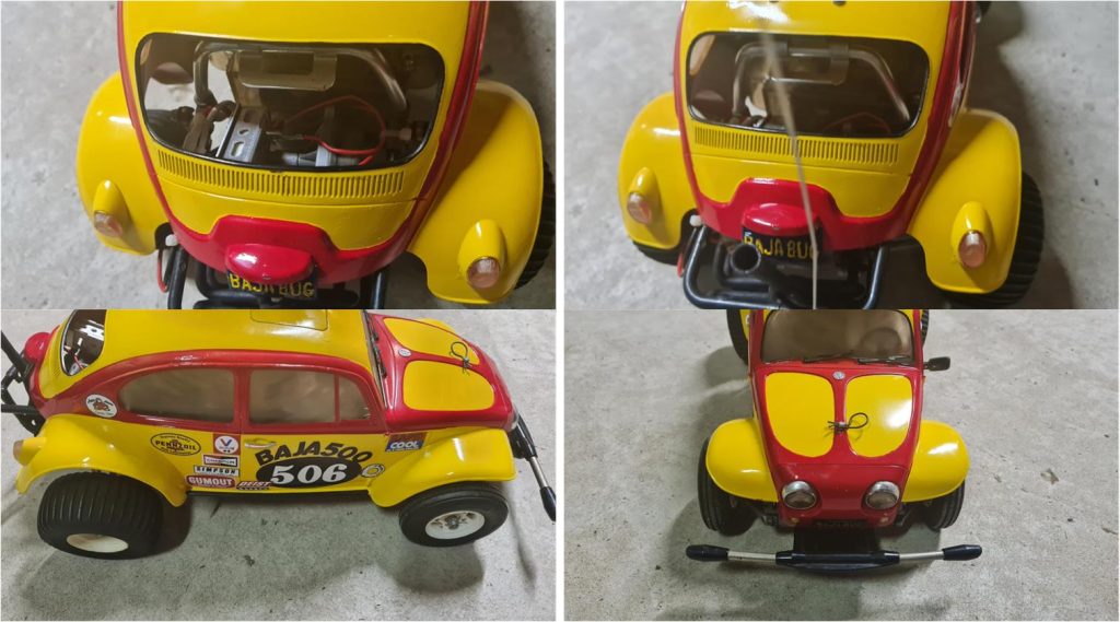
It is time to check the condition of the body. The body viewed from below and above (images in the first row) shows no damage and essentially retains its main components, including the system that locks the body to the rear roll bar (image on the right in the first row). The two rear lights are attached to the body, complete with lenses and integrated into the body’s contour (images in the second row), so a careful and delicate disassembly will be necessary to avoid damaging the transparent parts. The two main front headlights and the two turn signals are present (image on the left in the third row; the turn signals are typical of model 58016 and are absent in later editions such as the Monster Beetle model number 58060). The drip rail (image on the right in the last row) shows some damage, but it is not worn out as seen on some bodies; this is the part that wears down the most during rollovers.
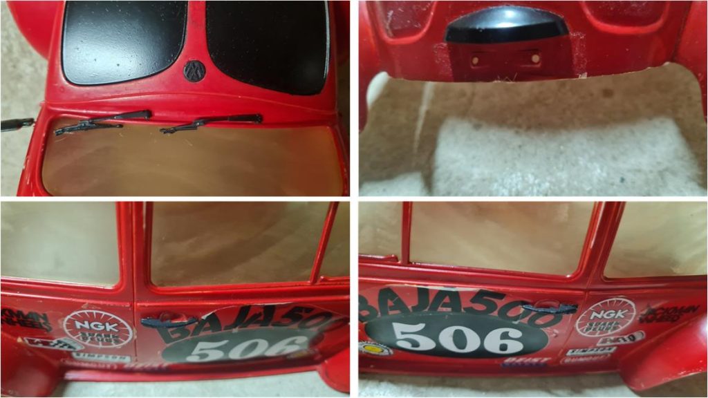
Most of the body accessories are also present; the driver’s side mirror and windshield wipers are included (image in the first row on the left, but the passenger side mirror is missing). Mirrors and wipers are the parts that detach most easily. The Volkswagen logo is present on the front hood. The license plate light guard is also included (image in the first row on the right), as well as the right and left door handles (image in the second row). All these parts are black, whereas they were originally chrome-plated from the factory. The first step will be to carefully detach them from the body and then they will need to be painted gray.
Chassis restoration
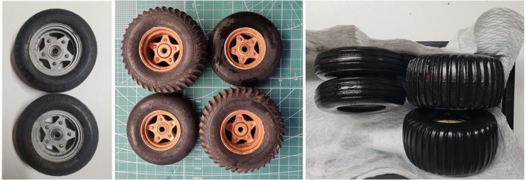
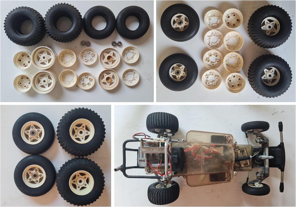
The goal of this restoration is to carry out a conservative restoration: the chassis will be inspected by cleaning its various parts and any missing or non-compliant components for an Mk1 will be replaced or rebuilt. At the end of the process, the chassis should appear tidy and be fully functional, without looking brand new; it must conform to the factory specifications of its era. The first issue to address is that the front and rear tires are not original. Upon removing the tires from the chassis, it is evident that the chassis has been fitted with ball bearings (left image). From previous projects, a complete set of tires is available (center image) that match the factory specifications. These tires need to be separated from the rims and subjected to a glycerin regeneration process (right image). This section explains how to rejuvenate rubber parts that have aged over time. For the rear tires, the central part of the rear rim is tightly embedded within the rubber. Removing it could damage the tire itself, so it is possible to proceed without removing the insert from the rear tire, as the glycerin treatment does not negatively affect the plastic of the rim.
It is time to disassemble the chassis down to every small part to search for hidden damage, incorrect hardware and concealed breaks. The front section is typically the one that suffers the most impacts; once disassembled piece by piece, no visible breaks are evident (image on the left in the first row). There are traces of heavy use of thread-locking fluid (image on the right in the first row). Fortunately, after all this time, the thread-locker has lost much of its grip, so the screws can be removed without difficulty. The bumper has endured several impacts but remains intact (image in the second row).
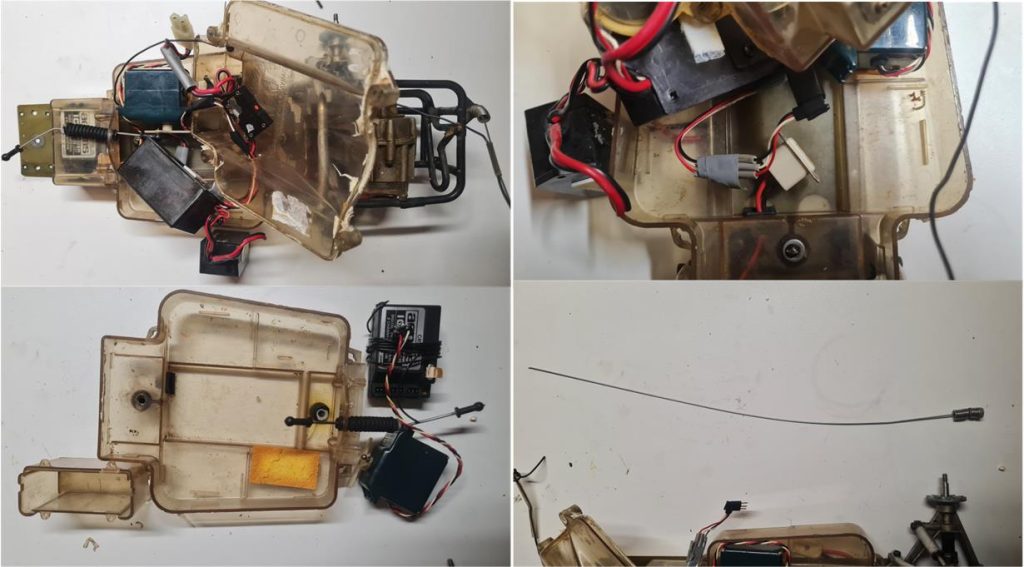
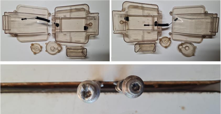
The central electronics housing has been sealed with silicone (image on the left in the first row); over time, the silicone’s grip has weakened, but it still holds the two parts together, remaining adhered to one of the surfaces. Mechanical action will be required to remove the silicone strip. The three transparent plastic parts are in excellent condition (image on the left in the second row). The electronics setup is fairly complex, featuring a motor speed control system that appears to be an early electronic controller. The mechanical speed regulator is missing, but a safety switch against short circuits and the antenna are present (image on the right in the second row).
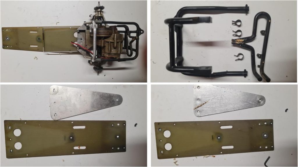
The torsion bars of the rear suspension are in perfect condition (image on the left in the first row). The same cannot be said for the plastic roll bar installed to protect the gearbox housing; beneath the black adhesive tape there is hidden damage. However, the structure is intact and it was necessary to evaluate whether to repair the damaged area using an acetone and styrene solution or to replace it (in the end, replacement was chosen). The exhaust set includes the three metal clamps used to mount it onto the roll bar. The rectangular FRP (Fiber Reinforced Polymer) plate and the triangular aluminum plate are in excellent condition and show minimal signs of wear.
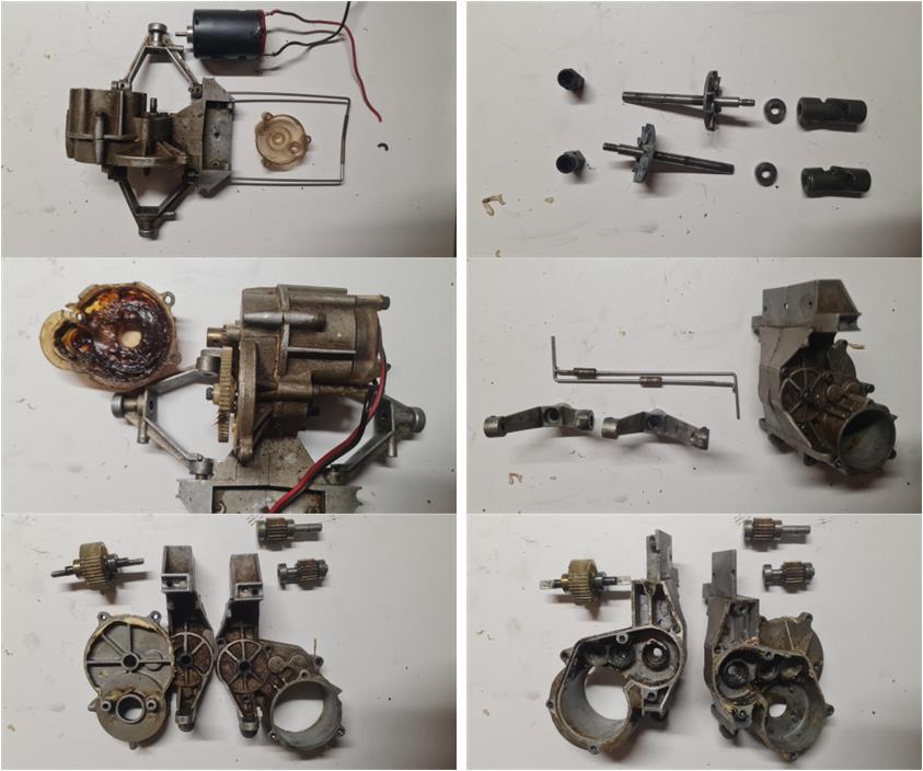
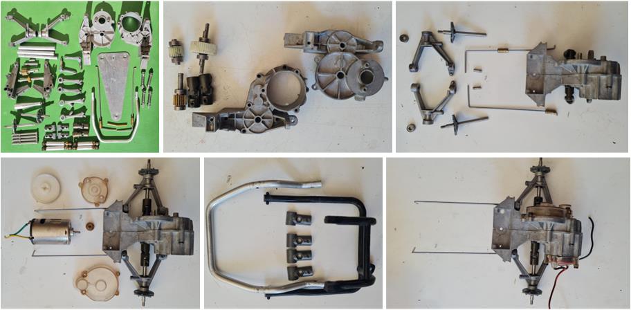
The electric motor is a surprise because it’s not the standard RS540, but the RS540SD Black Motor, accessory number 50189 (image on the left in the first row). Additionally, the previous owner installed bushings on the inner side of the wheel axles and used two plastic spacers to keep them in place, which are included in set number 50069 Bush Set for F1 and Countach chassis (image on the right in the first row). There has been heavy use of grease and the transparent plastic cover protecting the gear ring and pinion will need to be cleaned (image on the left in the second row). In the image on the right in the second row, you can see the circular recesses inside the lower suspension arms where the previous owner installed the bushings. These recesses are found only in the rear lower arms of the Mk1 model. The plastic spacers from set 50069 are used to hold the bushings in place. The gears are in perfect condition and equipped with ball bearings. The housings are intact but covered in grease and dirt.
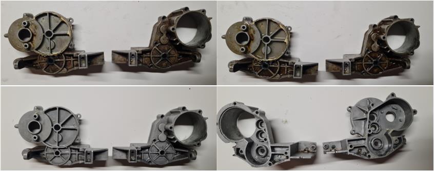
First, inspect all the hardware; in an Mk1, all screws must have slotted heads. This set includes many types of screws that vary in diameter (2, 3 and 4 mm) and length. Over the years, it’s common for screws to be replaced during routine maintenance and there’s a good chance they were swapped with Phillips head screws. For this model, it was possible to source all screws matching the original factory specifications. The metal parts are covered in dirt and grease. To clean them, WD40 lubricant can be sprayed onto the metal surfaces; it dissolves grease and prevents rust and corrosion while protecting the metal. In the image on the left in the first row, the two gearbox shells are shown as they appear immediately after being removed from the chassis. In the image on the right in the first row, the parts have been generously sprayed with WD40. The images in the second row show the parts completely cleaned and the WD40 film gives them a glossy finish. This film will protect them from rust and oxidation for a long time.
The same treatment is applied to all metal parts such as the lower triangular plate, suspension arms, front towers, rear axles and others. The components forming the electronics housing and the two shells covering the gear ring, pinion and rear section of the electric motor are made of transparent plastic. These parts can be cleaned using hot water and degreasing kitchen soap. To remove the residue from the double-sided tape used to secure the two servos, a cloth soaked in alcohol can be used to dissolve the adhesive. The pins that hold together the lower and upper shells of the electronics housing are made of aluminum and tend to wear or get damaged, as aluminum is a soft metal. It is possible to use pins from the re-release to replace the originals, but the original version pins have a slot on the head (pin on the left in the second row), which is missing in the re-release version (pin on the right in the second row). In this case, all four original pins are present. Although the original pins are not in perfect condition, they can still be used for this conservative restoration.
The metal parts have been cleaned and degreased (image on the left in the first row), the plastic components are now perfectly transparent and free of dirt and the hardware has been sorted and supplemented with the missing screws… it’s time to begin assembling the chassis. The chassis construction starts with the gearbox assembly, which includes the motor, suspension, protective shells and rear roll bar.
For a conservative restoration of this Mk1 chassis, it was decided to retain the performance-enhancing accessories that were originally installed—accessories featured in guide books from the late 1970s and early 1980s. All ball bearings have been serviced and the RS540SD Black Motor, accessory number 50189, has been installed. To refurbish the ball bearings, they were soaked in WD40 for a week to dissolve grease and dirt. The gearbox assembly also includes the suspension system and must be connected to the lower central FRP plate.
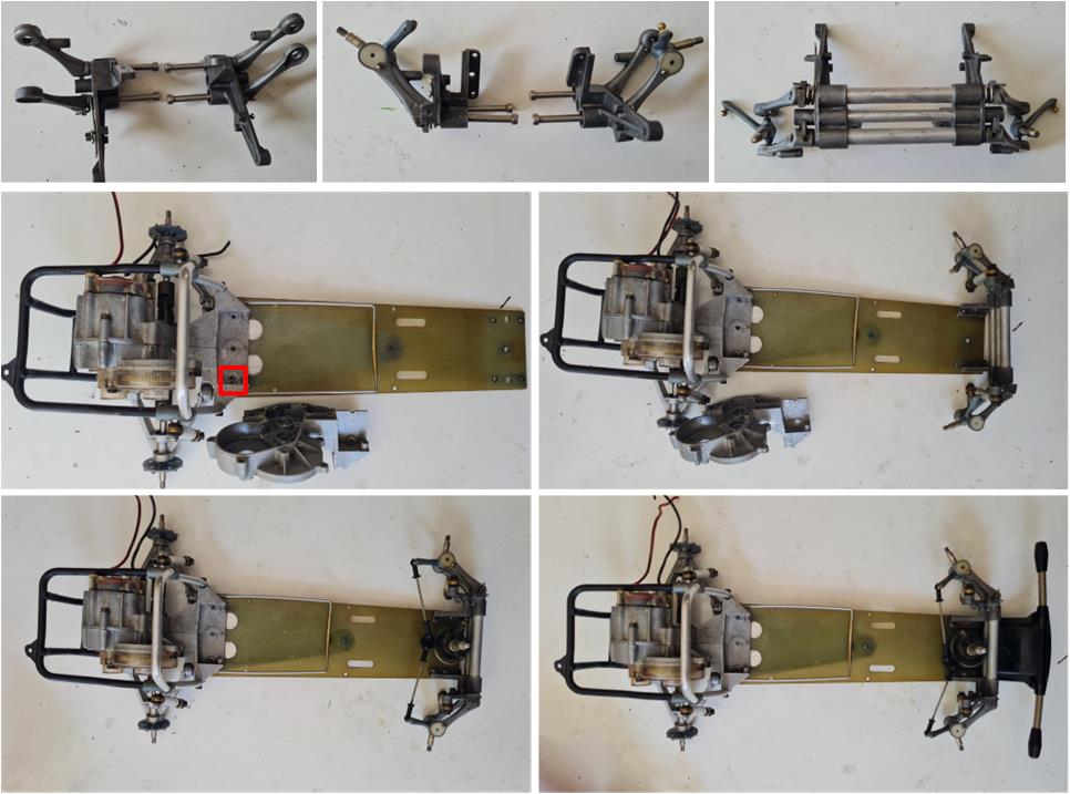
The double wishbone front suspension system also includes the steering mechanism and is entirely made of metal (first row). While installing the rear gearbox onto the central FRP chassis, a previously unnoticed issue emerged: the tower where the hex screw secures the right shell to the FRP chassis is missing. In the image on the left in the second row, the shell features the threaded tower at the front, while in the image on the right, the shell lacks this threaded tower. It is possible to replace the integrated tower with a bolt (see red box), but since an intact Mk1 shell is available, this part was replaced by disassembling and reassembling the entire section. The front assembly and bumper were then installed onto the FRP plate (images in the third row).
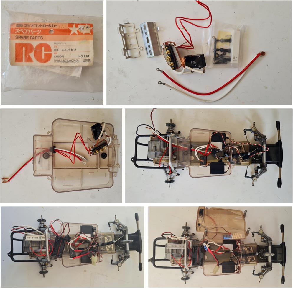
The mechanical speed controller was completely missing, but from previous projects, an unused new set 113 was available and used for this restoration. In the first row, the image on the left shows the label with the identification code and description, while the image on the right shows the contents that were installed inside the plastic electronics housing. Route the wiring through the cable guides and then mount the electronics box onto the FRP chassis. Now it’s possible to proceed with the electrical connections, install the servos using double-sided tape and mechanically connect the linkage system for the steering mechanism.
The tires have undergone the glycerin treatment. They were elastic enough to allow removal of the central insert from the rims and now it’s time to assemble the plastic rims and tires. The rims were degreased with alcohol to remove dirt and restore the plastic’s shine. They were not painted white, as the instruction manual specifies that the rims should remain uncolored. Once the wheels are assembled, they can be installed on the chassis, which is now ready for the body.
Body restoration
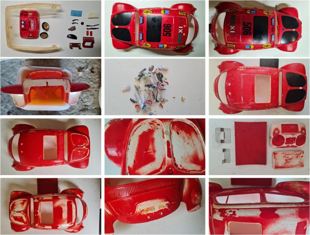
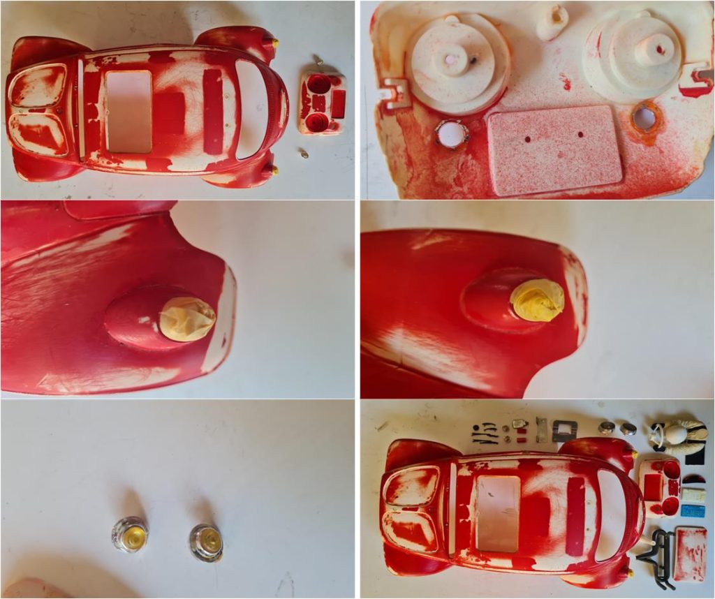
The body is in good condition, but the colors are incorrect. All parts are present except for the passenger side rearview mirror. This will allow for an almost perfect Mk1 model with the yellow–red color scheme. First, remove all accessory parts (top left image in the first row); the body is now bare and ready to be immersed in 99% pure alcohol (left image in the second row). Alcohol first attacks the adhesive, allowing the stickers to be removed (center image in the second row) and also loosens the glue of parts that couldn’t be disassembled earlier (such as the black roof in the right image of the second row). With multiple alcohol baths and mechanical action using kitchen paper, it’s possible to remove the less resistant paint (black and part of the red). The same treatment is applied to the nose and the opening roof. Using wet 3,000-grit sandpaper (left image in the third row), the damaged areas of the body caused by rollovers—such as scratches on the roof and fenders (images in the last row)—can be smoothed out. Refer to the guide on how to use sandpaper on styrene bodies.
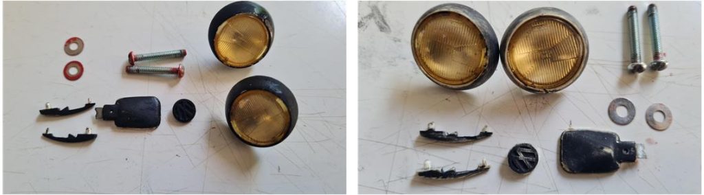
The chrome parts of the headlights, door handles, Volkswagen logo and rearview mirror were covered with black paint. The paint dissolved after washing the surfaces with hot water and kitchen soap. Fortunately, the black paint used on these parts was of lower quality compared to the red paint on the body, which was not affected by the alcohol. This made it possible to preserve the chrome finish on these small components.
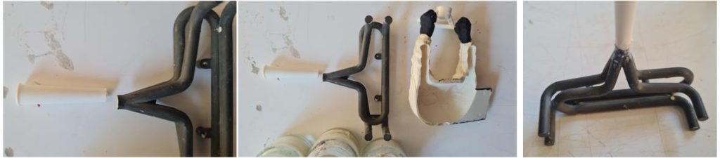
The terminal part of the engine exhaust is missing; in the 2010 re-release, this part is included and identical to the original. From set number 19115270, the trumpet (white part in the image below) was taken. To attach it to the rest of the original exhaust, a solution of acetone and ABS was used, which fused the parts together. After 48 hours from the application of the solution, the surfaces were treated with 1,000-grit sandpaper to eliminate any imperfections.
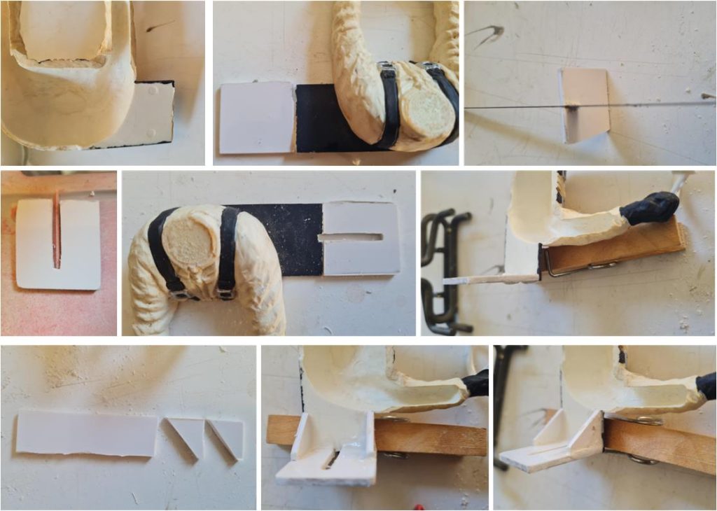
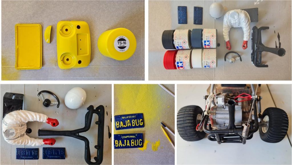
The driver figure is original, but the L-shaped bracket needed to mount it to the body is missing. Since it’s sufficient to reconstruct the missing part, it’s better to proceed with fabrication rather than using the re-release driver from set number 19115270. Cut a rectangle from a 2 mm thick ABS sheet, using the body and the driver figure as reference (center image in the first row). Cut a slot in the center to mount the driver to the chassis; use a saw to make the slot (right image in the first row), then widen it with a flat metal file. Work the parts until they fit perfectly onto the body (left image in the second row). Weld the pieces together using an acetone and ABS solution. To reinforce the structure, install two brackets shaped as 45° isosceles triangles (left image in the third row).
Alcohol made it possible to detach the various parts; only the rear lights remained firmly attached to the body (images in the second row). The front turn signals were the last to come off (image on the left in the last row). Now the parts are ready for the primer coat (image on the right in the last row).
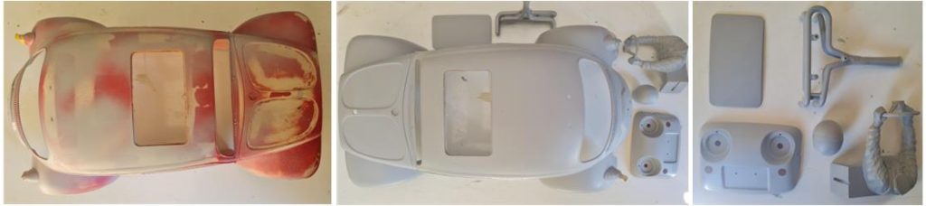
The primer should be applied in multiple coats, with the first layers kept light (left image). The primer must cover all surfaces evenly, otherwise the final color result will be affected (center and right images).
The styrene body is red and yellow; apply the lighter color first (TS16 yellow). If the darker red were applied first, the yellow would be affected, appearing almost orange. Refer to the guide on how to paint styrene parts. The driver figure has a white body (XF2), red gloves (XF7), black seat belts (XF1) and metallic parts of the buckle in silver (metallic grey XF56). The helmet is white (X2) with a black seal (XF1). The steering wheel has a black rim (XF1) and silver spokes (metallic grey XF56). The exhaust is black (XF1); once completed, it can be installed on the rear roll bar (image on the right in the last row). The license plates are royal blue (X3) with lemon yellow letters (X8). Even using the toothpick tip technique, painting the letters is truly a titanic task; a magnifying glass would be needed.
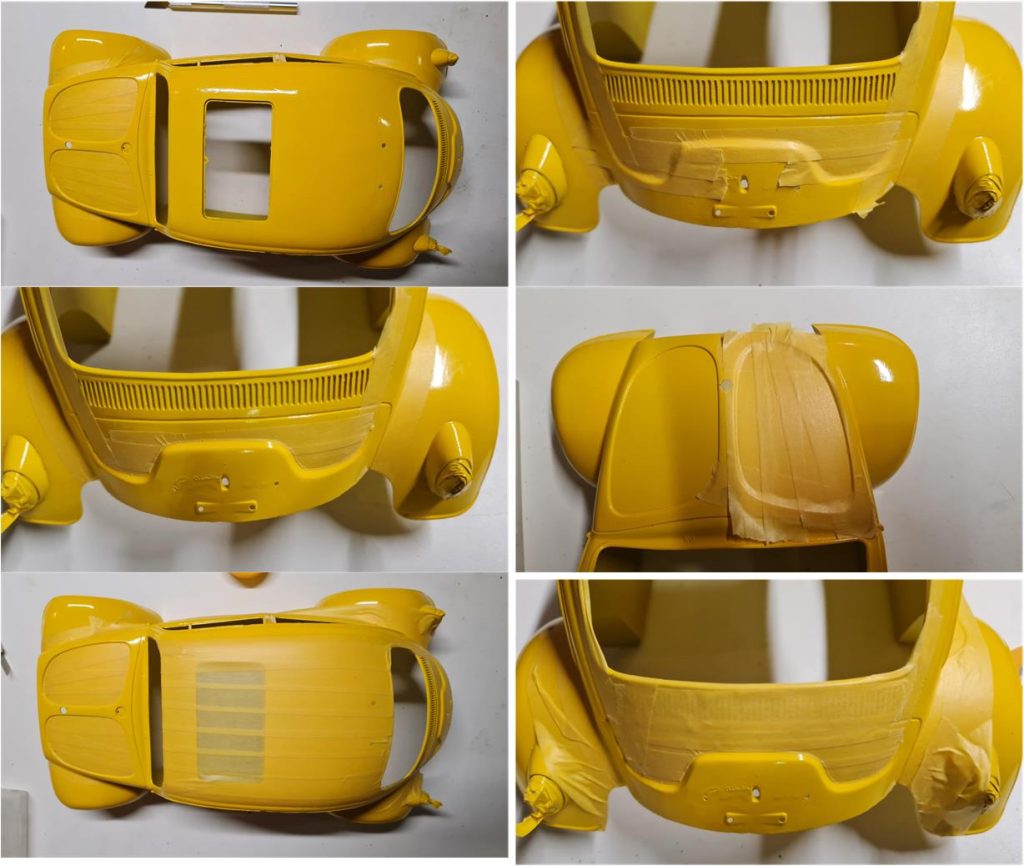
After a week since the yellow paint was applied to the body (image on the left in the first row), it is now possible to begin masking the areas that will remain lemon yellow. The transparent rear lights were masked before applying the yellow. It is necessary to wait at least one week after the final yellow coat to ensure the paint is fully dry and won’t be affected by the solvents in the red paint. Once the lines are masked, the entire body that should remain yellow must be covered. To mask the two ovals on the hood, first cover the entire hood (image on the right in the second row), then cut out the shape using a scalpel (image on the left in the third row). Repeat the same process for the rear section (full masking shown in the image on the right in the first row and the cut-out section in the image on the right in the third row).
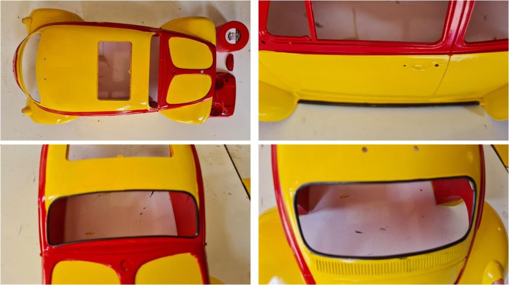
Apply TS8 red to the body covered with masking tape. Start with one or two light coats, then proceed with heavier coats to cover all surfaces. After applying the final red coat, remove the masking tape within 2 to 4 hours. Removing it earlier may damage the red layer, while waiting too long may cause pieces of hardened paint to peel off with the masking. Finish the window seals and door sills in black (XF1).
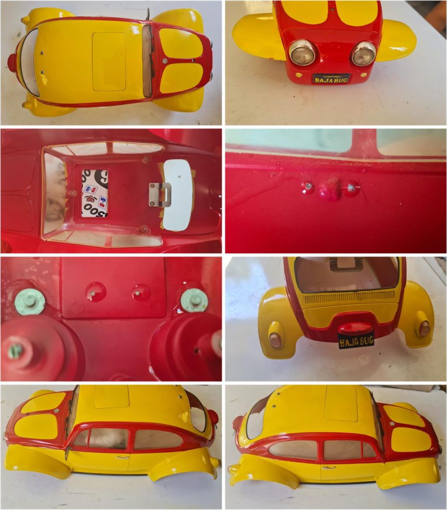
Now it’s possible to install the parts that complete the body: driver figure, windshield wipers, driver’s side mirror, Volkswagen emblem, license plate light holder, turn signals and front nose with headlights. Use UV-curing glue, which remains flexible and will make it easier to detach the parts in the future if needed. Apply a drop from the inside and let it cure; in summer, the piece can be exposed directly to sunlight to complete the transformation of the glue from liquid to solid.
Now the decals can be applied and the body is ready to be joined with the chassis.
Restored model with body
Images showing the completed model with the body installed.
Tamiya, original figure, box art, guide book and catalogue are of TAMIYA INC, which does not endose or sponsor www.tamiyaclassic.com. Any brands, logos and trademarks represented on this website are the copyright of their respective owners.