Model
Tamiya Porsche 959, model number 58059, released in 1986 and available on the market until 1992
Lexan body shell, 1/12 scale.
959 chassis
The body shell of the Porsche 959 has a shape featuring curves and bulges on the front, sides and rear. These shapes are impossible to obtain with a traditional mold. To produce this complex body shell, Tamiya uses a special manufacturing system in which, at the end of the forming process, the mold breaks down into several pieces to allow the body shell to be extracted using a complex air‑blowing system.
The body shell is enhanced with ABS details to make the reproduction even more realistic (rear wing, dual‑exit exhaust, two roof‑mounted brake lights, co‑driver side mirror, driver side mirror, working front light system, cockpit with driver and co‑driver). The front light system consists of two bulbs connected to the main battery through the connector coming from the mechanical speed controller (part number 50307 described as “3 Step Forward/Reverse”), released only for this chassis.
The following were released for sale:
– two chassis versions differing in a few technical details (see 959 chassis guide) and
– two liveries differing only in the main sponsor: in the early years the Rothmans brand (a cigarette and tobacco brand) was present, later replaced by a more generic “Racing”.
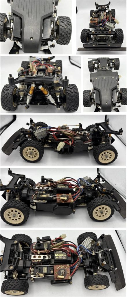
The Porsche 959 chassis is as compact as it is complex, which makes it very fragile: it consists of the front and rear gearbox housings connected by the central section. Four‑wheel drive system with independent suspension (the lower arms are among the most delicate parts ever produced by Tamiya; today in 2026 they are practically unobtainable unless turning to the 3D‑printed parts market).
To keep the weight around the center of gravity and improve the chassis’ dynamic performance, the central section houses the receiver, the electronics consisting of the two servos for the steering system and the mechanical speed controller, the battery, the mechanical speed controller and the electric motor (the Technigold RX540‑VZ is supplied for the first time as standard).
The four dampers were released only for this chassis; they are aluminum with a plastic tube serving as the oil reservoir (as of 2026, they have never been used on any other model).
It is difficult to find models on the market in good condition at an affordable price; many models hide broken parts or 3D‑printed reproductions. For this project, several lots of parts, chassis and body shells have been collected over the years. The goal was to gather as many original parts as possible. The collected parts allow assembling at least two complete 58059 models (one in the Mk2 version and one in the Mk1 version) and one 58064.
Project
Construction of a chassis made as much as possible from new or like‑new parts to assemble a chassis with a body shell suitable for display on a shelf or inside a showcase. The project involves building a 959 Mk1 chassis in the Porsche 959 configuration complete with the only three accessories Tamiya released:
– part number 50322 described as “Toyota Celica Gr.B Front Stabilizer Set”
– part number 50323 described as “Toyota Celica Gr.B Centre Differential Set”
– part number 50324 described as “Toyota Celica Gr.B Propeller Shaft Set”
These accessories are part of the standard equipment of the Toyota Celica Gr.B model number 58064; for the future owner, the original parts are stored together with the model.
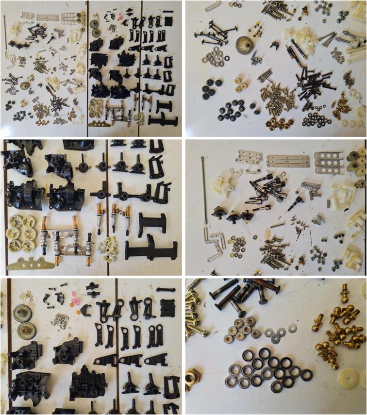
Collecting the individual pieces needed for this project took years; buying lots of parts, incomplete chassis, destroyed or cannibalized chassis. Here is a more or less complete list of the available parts.
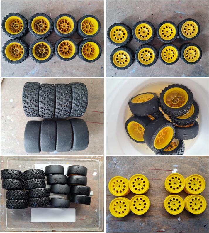
Two complete sets of tires were collected:
- one road set with slick tires (set number 50309 described as “Porsche 959 Slick Tyre With Wheel”) and
- one off‑road set with treaded tires (set number 50308 described as “Porsche 959 Rally Tyre With Wheel”).
The tread on all eight tires is not worn and shows no cuts or tears. The rims show no major impact damage. The tires are stiff; to help them regain some elasticity, treat them with glycerin (image on the right of the second row). Follow the guide explaining how to treat the tires with glycerin. The treatment is divided into four phases; the first phase lasts only a few minutes, while the remaining three phases last one week each, for a total of three weeks of work: the first phase is general cleaning with warm water, the second phase involves immersing the tires in a container filled with glycerin, the third phase is natural draining of the glycerin and the final phase involves drying all remaining droplets emulsified by the rubber using a kitchen paper towel.
The rims were washed with kitchen degreasing soap and warm water; in the last image at the bottom, the four rims on the right are new.
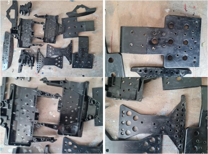
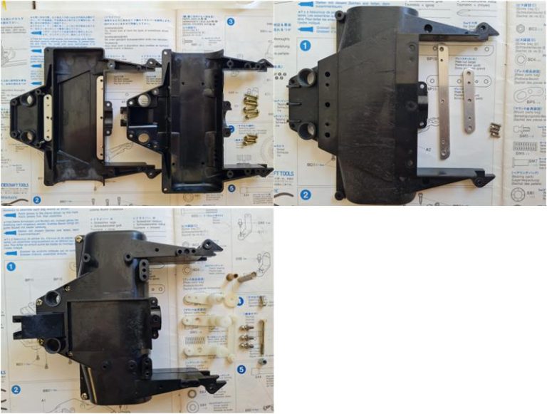
For the construction of the chassis, several plastic parts were collected; for this project it is necessary to pay maximum attention to avoid damaged parts, non‑original parts or those modified by previous owners. For example, a complete lot was set aside because the previous owner (presumably to lighten the chassis) drilled holes in the two shells forming the central section, in the T‑shaped front undertray and in the I‑shaped rear undertray. These parts cannot be used for this restoration. However, over time it was possible to collect a large amount of material, so the complete B‑part set (the two T‑ and I‑shaped undertrays) is available new: part number 0005262 or X‑9959.
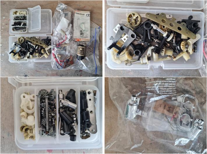
Several loose parts are present; all these components are intact and there are also some suspension arms (see images in the first row). This is the rarest section because these arms tend to break when the model performs jumps, making intact ones very difficult to find.
The front fiberglass plate for the two body‑mount towers is present, along with a complete gear set, the alloy plates used to stiffen the chassis, the white Teflon parts, the wheel hubs, a Technigold motor, a front lighting system with the structure used to install the lights on the body shell (image on the right of the second row), a mechanical speed controller with the connector for the lights and many other small parts.
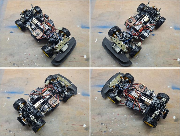
In addition to these loose parts, there is a partially complete chassis, but it has some broken suspension arms. The front gearbox housing, the rear gearbox housing, the central section and the front and rear undertrays are intact. The front anti‑roll bar is present, part number 50322 described as “Toyota Celica Gr.B Front Stabilizer Set”. This set is standard on the Toyota Celica Gr.B, item 58064, but it is an accessory for the Porsche 959, model number 58059.
After disassembling the chassis, it is also clear that the ball‑type centre differential is present, part number 50323 described as “Toyota Celica Gr.B Centre Differential Set”. This set is also standard on the Toyota Celica Gr.B, item 58064, but it is an accessory for the Porsche 959, model number 58059.
A second chassis is also present and it is a mystery because it is a mix of 58059 and 58064 solutions:
– the front stabilizer bar is the version intended for the base configuration of the Toyota Celica Gr.B number 58064
– the reinforced rear undertray is the version intended for the base configuration of the Toyota Celica Gr.B number 58064
– the front undertray is the version intended for the base configuration of the Toyota Celica Gr.B number 58064
– the four white rims are the version intended for the base configuration of the Toyota Celica Gr.B number 58064
– the rear support for the two body‑mount posts is the version intended for the base configuration of the Toyota Celica Gr.B number 58064
– the front support for the two body‑mount posts is the version intended for the base configuration of the Toyota Celica Gr.B number 58064
– the front bumper is the version intended for the base configuration of the Toyota Celica Gr.B number 58064
– the position of the resistor for the mechanical speed controller is the version intended for the base configuration of the Toyota Celica Gr.B number 58064
– the fixed gear is the version intended for the base configuration of the Porsche 959 number 58059
– the propeller shaft between the front and rear gearbox housings is the version intended for the base configuration of the Porsche 959 number 58059
The mix of solutions is truly unusual: it is unclear whether this is a Porsche upgraded with several Toyota Celica Gr.B parts or a Toyota Celica Gr.B onto which the fixed differential and standard propeller shaft of the Porsche 959 were installed (these two parts are certainly not performance‑enhancing accessories).
The Toyota Celica Gr.B parts will be used to restore a 58064 chassis.
The presence of a chassis that was probably originally a Celica Gr.B matters little for the ongoing restoration, since only the individual parts needed to build a Porsche 959 are relevant; any non‑compliant parts will not be used.
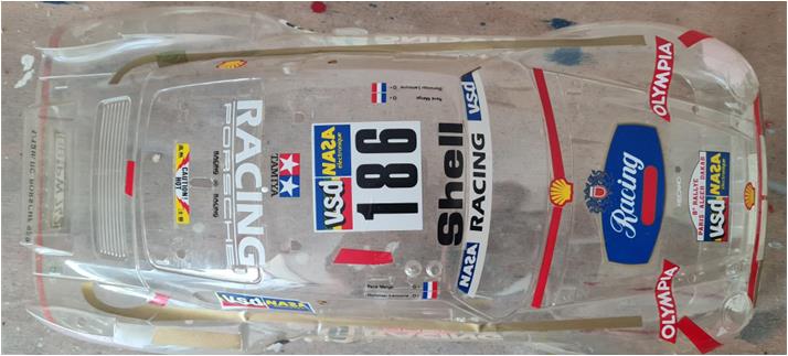
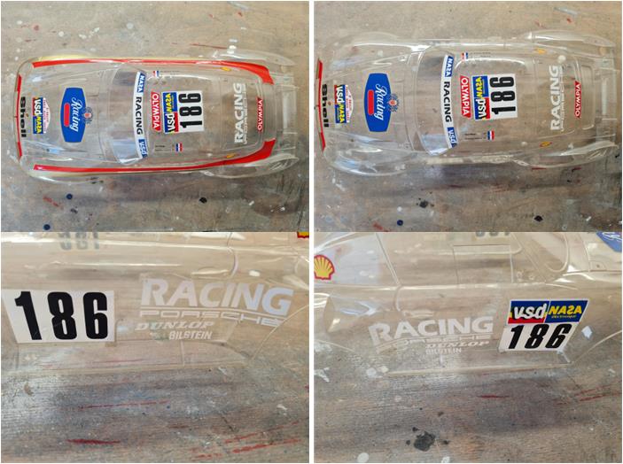
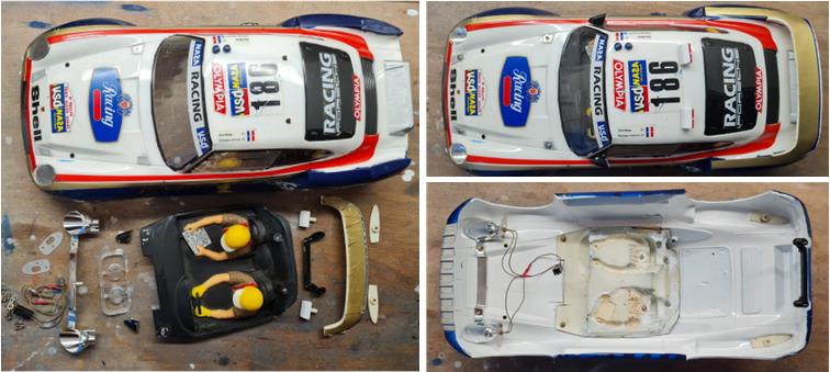
From the previous restoration of a 58059 Mk2 chassis, a complete and undamaged body shell was set aside for this project, although the decals were applied without following the instructions (image below), along with an original interior cockpit, a front lighting system and a complete set of ABS parts consisting of the two rear‑view mirrors, the exhaust outlet, the rear spoiler, the full cockpit assembly and the twin roof‑mounted lights.
The chassis configuration corresponds to that of the Toyota Celica Gr.B, which differs from the Porsche 959 in the following parts:
– T‑shaped rear undertray
– I‑shaped front undertray
– anti‑roll bar installed on the front axle (developed specifically for the Toyota Celica Gr.B; for the Porsche 959 it is available as an accessory, part number 50322)
– central position of the power resistor for the mechanical speed controller
– front plate for the body‑mount towers
– ball‑type centre differential (developed specifically for the Toyota Celica Gr.B; for the Porsche 959 it is available as an accessory, part number 50323)
– rear plate for the body‑mount towers
– propeller shaft transferring drive from the rear axle to the front (see image, developed specifically for the Toyota Celica Gr.B; for the Porsche 959 it is available as an accessory, part number 50324)
Assemble the chassis
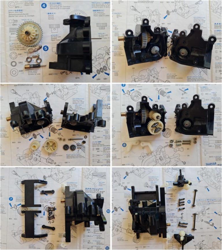
These are the parts that have been restored so they can be used in this project. Wash the plastic parts with hot water and soap. Use a toothbrush to reach corners and the most hidden areas where the most stubborn dirt accumulates.
Leave the metal parts immersed in diesel fuel for one week; the diesel dissolves oxidation, grease and dirt. After the diesel treatment, leave the parts in the sun for one day. At the end of the process, the metal parts will be coated with a thin film of oil that protects them from oxidation.
The central section of the chassis is slightly marked by time in the area that comes into contact with the ground between the I‑shaped and T‑shaped undertrays. Use polish and wax to remove the shallow scratches and restore shine to the plastic surface. Assemble the central part of the chassis, which is made of two shells.
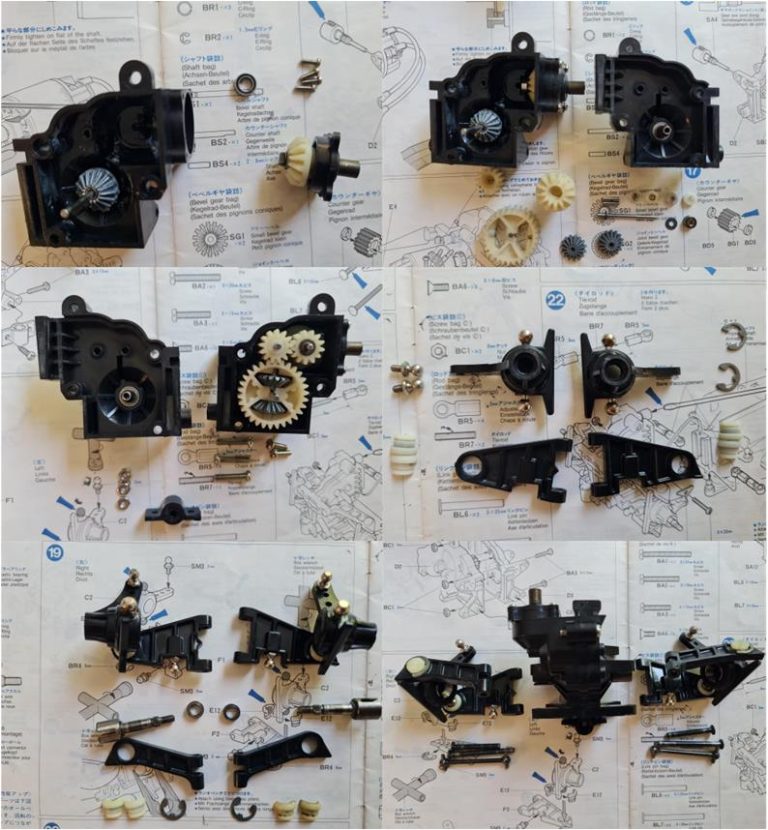
Assemble the rear section, which includes the rear differential housing and the motor pinion. In this case, the ball‑type centre differential is also installed, part number 50323 described as “Toyota Celica Gr.B Centre Differential Set”. It is a performance‑enhancing accessory released with model 58064.
Join the rear section with the central section by installing the Technigold RX540VZ motor
Complete the front section, which includes the differential and the steering system. Only the right lower arm is from the Mk1 version. At the moment, the two steering knuckles (image on the right of the second row), the upper arms (image on the left of the third row) and one lower arm are from the Mk2 version (image on the right of the second row). Some of these parts will be replaced with the correct ones before completing the restoration.
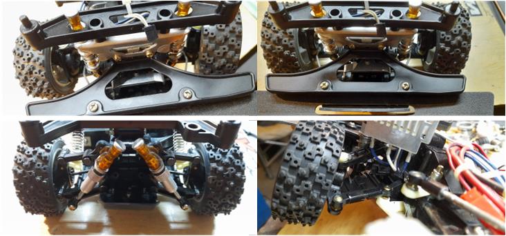
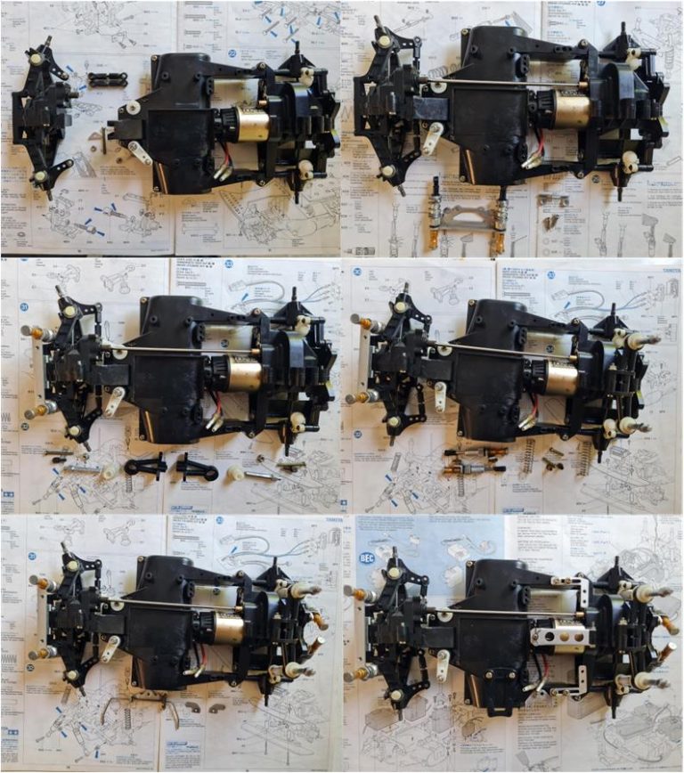
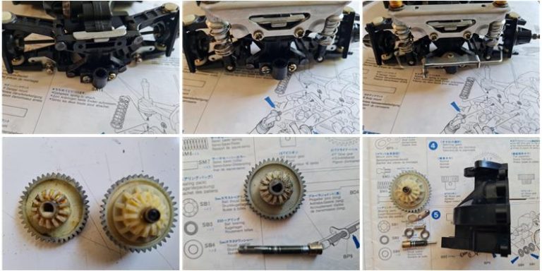
Join the front section with the sub‑assembly formed by the rear and central sections. Install accessory number 50324 described as “Toyota Celica Gr.B Propeller Shaft Set”; this is the driveshaft that connects the front section to the rear section (image on the right of the first row). Install accessory number 50322 described as “Toyota Celica Gr.B Front Stabilizer Set”; this is the anti‑roll bar for the front axle (image on the left of the third row). Install all the parts for the towers that connect the body shell to the chassis.
Images (from the first row) showing how to install the front anti‑roll bar. First, separate the dampers from the lower arms to install the two L‑shaped plates at the height of the ball joint for the dampers on the lower arms. Reattach the dampers to the arms and then install the anti‑roll bar.
Images (on the left of the second row) show the comparison between the ball‑type centre differential and the fixed gear. The fixed central gear with its long shaft (centre image) is kept with the model in case you want to return to the factory configuration. Image on the right of the second row shows the installation of the ball‑type centre differential with the short shaft.
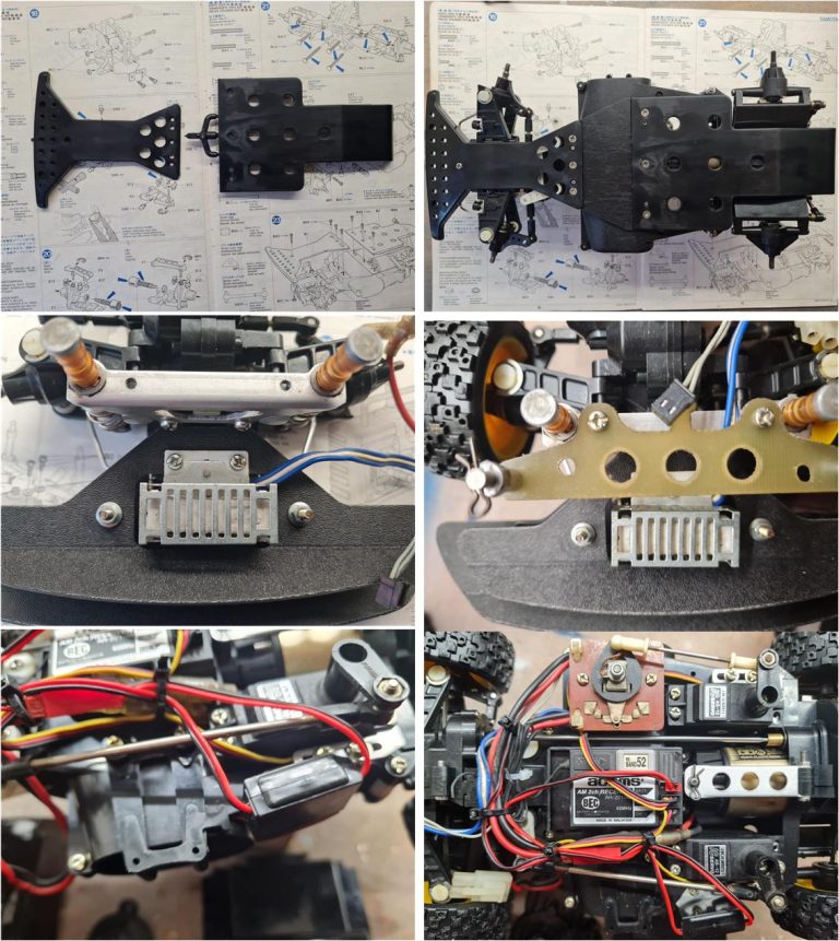
The shipment has arrived with the double lower plates, the I‑shaped and T‑shaped ones: these are brand‑new parts (image on the left of the first row). Install the two lower plastic plates (image on the right of the first row) and complete the electrical section, which includes the special speed controller for the 959 chassis with the connector for the front lights.
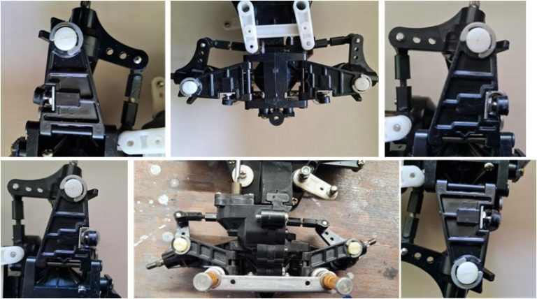
The front suspension is composed of two lower arms and two upper arms. In the Mk1 version, all four arms lack the characteristic steering end‑stop tab and the front knuckles also do not have the typical T‑shaped stop that prevents the knuckle from going beyond its steering limit (in the image of the first row the Mk2 knuckles are still visible, but the right arm is the Mk1 version). Three of the initially installed arms have been replaced (images on the right and left of the second row), as well as the two steering knuckles (centre image of the second row), with components matching the Mk1 specification. Only the lower arm in the first image remains in the Mk2 version (image on the left of the first row).
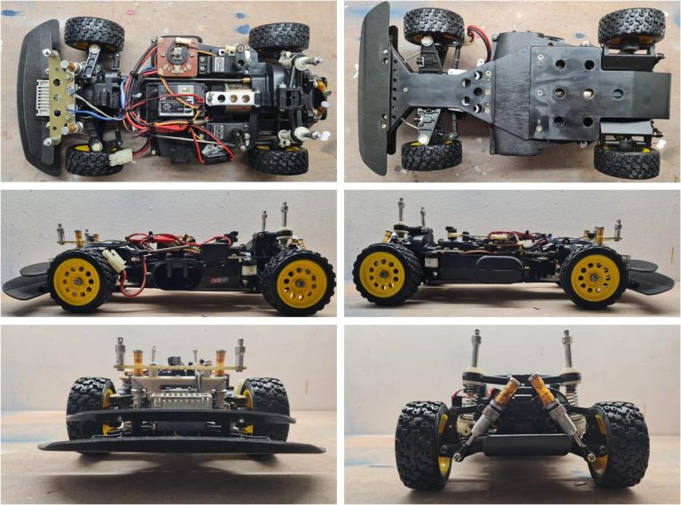
Images of the complete chassis.
Body
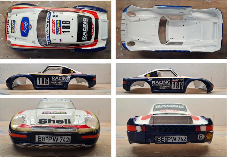
The body shell is new and perfectly trimmed. Someone applied the decals without following the instructions (image on the left of the first row). The first step is to try to save the decals that can be repositioned (image on the right of the first row shows the body shell with the decals that could be correctly repositioned). Carefully try to lift one corner of the decal; once the corner is large enough, it can be used as a grip point to fully remove the decal and place it in the correct position. Be careful, as the decal film is very thin and may tear during the operation. The adhesive is generally of high quality and withstands the process: it is possible to remove a decal and reapply it elsewhere on the surface (images on the right of the first row and in the second row show some of the relocations).
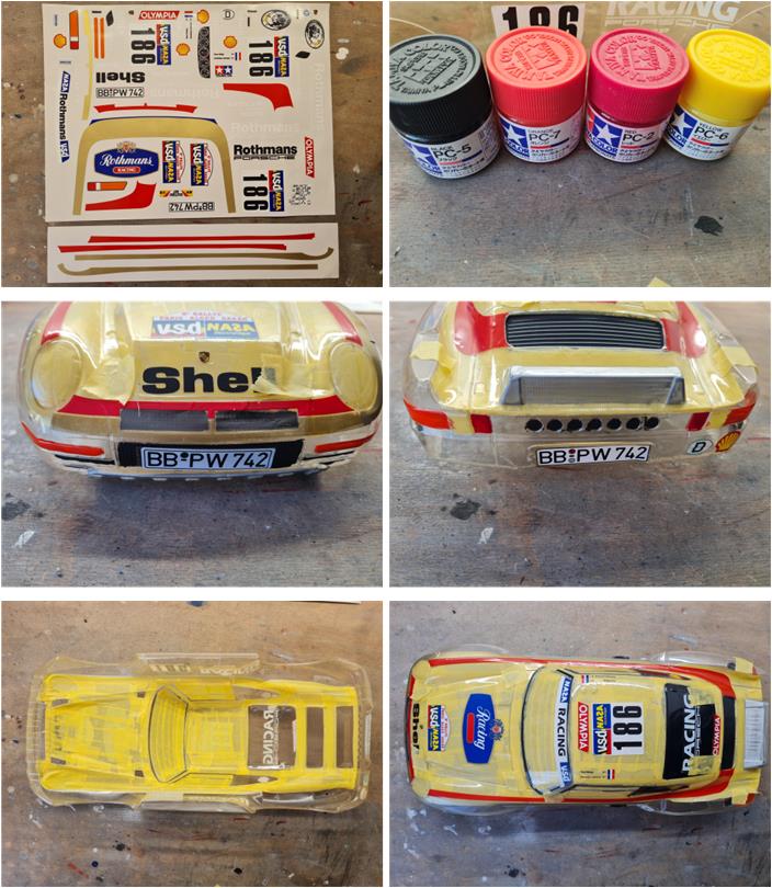
Only a few decals could be recovered; others were damaged or had been poorly cut by the first owner, making them unusable. A replacement set reproducing the original decals is available and as of 2026 several reproductions exist on the market; among the available options, choose the one that is the most faithful in colour.
Before applying the white and blue paint to the body shell, apply the red‑gold decal that outlines the area of the blue and white sections. This makes it easier to create the masking that separates the two colours. Before proceeding with the blue and white spray paints, it is necessary to use brush paints to colour the various details: PC7 orange for the front and rear position indicators, PC2 red for the rear brake lights, PC12 grey for the front bumper and rear radiator, PC5 black for the rear windows, the rear screen, the central front grille, the double grille on the bonnet and the rear and central side air intakes. After applying two or more coats of the brush colours, it is possible to define the area where the first spray colour will be applied.
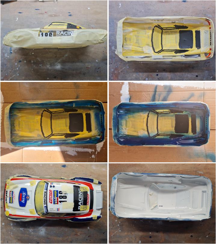
Apply the blue coats first (the darker colour) and then the white (the lighter colour); follow the guide that explains how to apply paint on transparent Lexan bodies. Since the outer protective film is missing (removed by the previous owner), it is necessary to protect the outside surface by applying masking tape (image in the first row). TS19 blue is the darker colour, so the first coats must be light to prepare the surface to receive the paint and to prevent overly wet paint from seeping under the masking. After applying the blue, remove the masking for the white area and apply TS26 white.
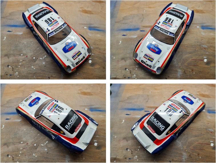
After applying several coats of white on the inside surface, remove the external masking from the body shell and what remains of the internal masking on the cockpit windows and the front lights. Images of the body shell ready to be completed with the ABS details.
Install the ABS parts: rear wing, twin‑exit exhaust, the two roof‑mounted brake lights, the co‑driver‑side rear‑view mirror, the driver‑side rear‑view mirror, the working front lighting system and the cockpit with driver and co‑driver. The lighting system is new and the lenses must be removed from the sprue.
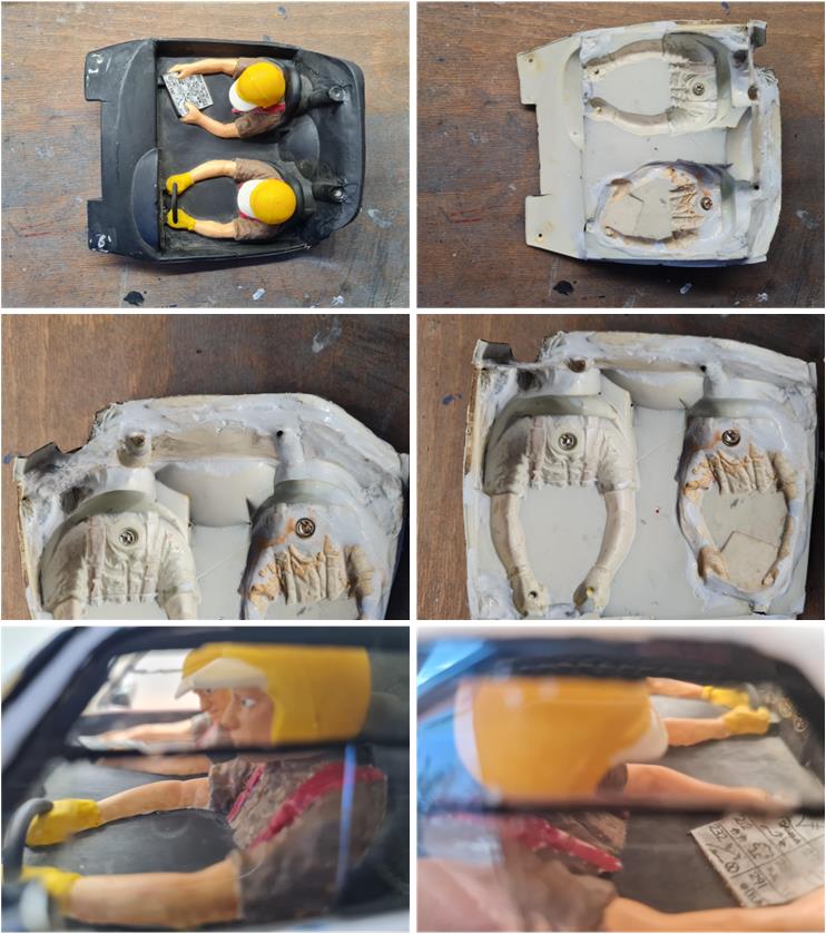
The cockpit has been repaired using an acetone‑and‑styrene solution (see the images on the right of the first and second rows). However, the visible part of the cockpit interior (image on the left of the first row), including the helmets and the steering wheel, is in perfect condition with the original decals (image in the last row).
Restored model
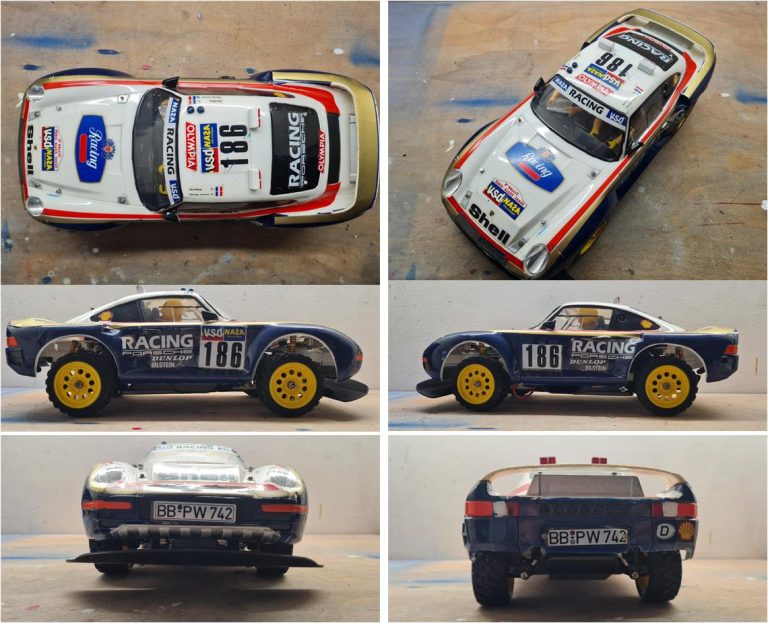
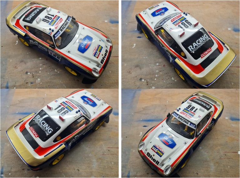
Images of the completed model.